This thread has been locked.

If you have a related question, please click the "Ask a related question" button in the top right corner. The newly created question will be automatically linked to this question.

INA280: any issue if the input common mode cap value is mismatched?

Part Number: INA280
Other Parts Discussed in Thread: TINA-TI, INA281

Customer used R=10ohm, with 0.1uF common mode cap for the input filter of INA280. But they found when the actual cap value is not well matched, such as with 3nF difference, the output of INA280 would show oscillation, and the amplitude would reduce. 

Do you think it makes sense?

  • Hello Aki,

    Normally the oscillations come with output capacitor.  The input I would not expect an oscillation with capacitor mismatch unless they are having large transients of VCM.  The mismatch makes sense as if one side changes much more than the other you do not see the same input.  Do the have a Vdiff capacitor?

  • Hi Aki,

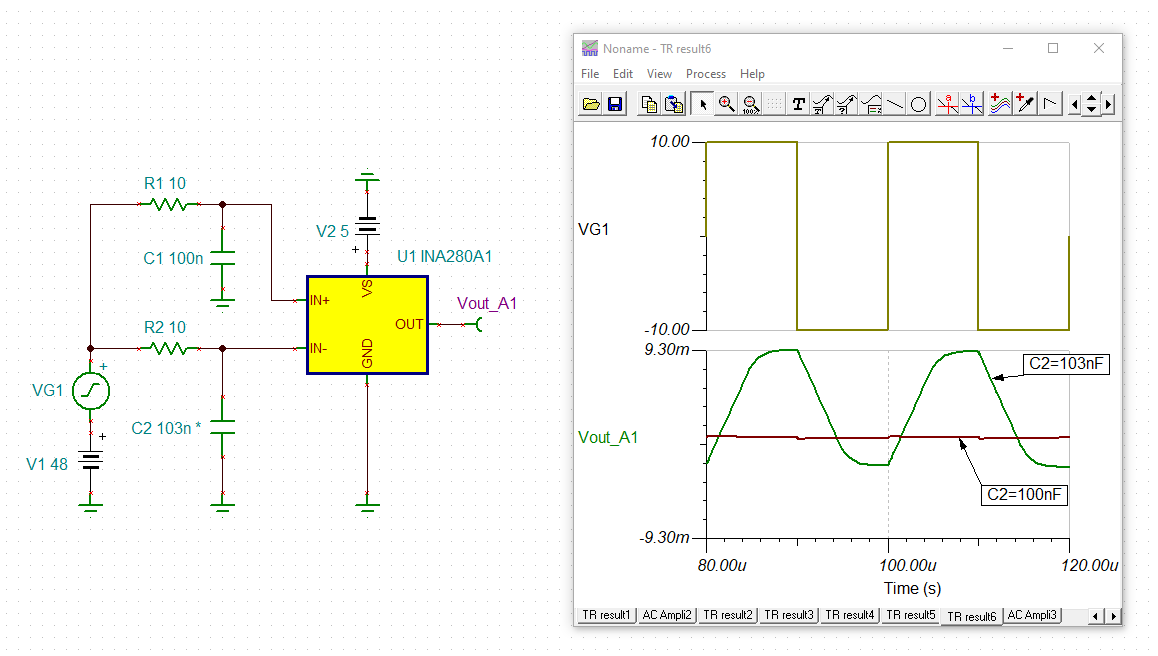
    any imbalance in the common mode input low pass filter will ruin the awesome common mode rejection of INA280. The TINA-TI simulation demonstrates that an imbalance of only 3% results in a degradation of common mode rejection of nearly 40dB!!!!!:

    aki_ina280.TSC

    I guess you have a common mode input signal looking like an "oscillation", which with a good balance of input filter (C1 = C2 = 100nF) is almost entirely suppressed at the output by the INA280, but becomes visible suddenly when there is an imbalance of input filter (C1 = 100n, C2 = 103nF) because of the degraded common mode rejection. This would look like an oscillation which seems to be caused by the imbalance of input filter. But in reality the "oscillation" is merely the consequence of a heavy degradation of common mode rejection.

    When it comes to common mode input filtering. "less" is sometimes "more". You should not choose all too high common mode filter capacitances, because the higher the capacitances the higher the degradation of common mode rejection. In any case the caps should be state-of-the-art referring to manufacturing tolerances, temperature drift and long term drift. Best use very narrow tolerated ceramic NP0 (C0G) caps. Also, avoid the introduce of additional imbalance by uneven stray capacitances at the input. Avoid any unnecessary cabling between the shunt and the INA280.

    Kai

  • Hi Kai, 

    Thank you for the detailed explanation. However, the common mode voltage was stable at 12V in customer application, just with some high frequency voltage ripples. Do you think it will also cause the output oscillation?

  • Hi Javier,

    There is no Vdiff cap. Do you think differentiated cap is more helpful than the common mode cap for the noise filtering purpose?

  • Hi Aki,

    There is no Vdiff cap. Do you think differentiated cap is more helpful than the common mode cap for the noise filtering purpose?

    I don't want to answer for Javier. But let me say this: Whether common mode filtering is more helpful rather than differential filtering depends on the nature of noise, ripple or EMI. If the noise is true common mode noise then only common mode filtering will help, but not diferential mode filtering and if the noise is true differential noise, on the other hand, then only differential mode filtering will help, but not common mode noise filtering. And while differential mode filtering can easily achieved by two filter resistors and a differential capacitor between the inputs of INA280, common mode filtering with two resistors and two common mode filtering caps is critical because of eventual imbalance of filtering time constants of common mode filtering. Experience has shown that common mode filtering at the inputs of INA280 can do more harm than good.

    However, the common mode voltage was stable at 12V in customer application, just with some high frequency voltage ripples. Do you think it will also cause the output oscillation

    If the high frequency voltage ripple is common mode noise and the common mode noise is incompletely suppressed by an imbalance of common mode filtering, then a copy from this noise can appear as output oscillation.

    Aki, all this more and more becomes an academic discussion. I would suggest that the customer performs some scope measurements of both input signals of INA280 and the output signal. We also should see a schematic to find out whether there is a too high capacitive output load causing instability and ringing. Also, please give more details on the application and tell us whether any cabling is involved at the inputs and the output of INA280.

    Kai 

  • Hello Aki,

    As always I agree with Kai.

    Could this actually be the current?  Have the tried removing the filter completely?  The more information the better help can be provided.  Like Kai suggested more information and schematic would help?  What is the current range and signal of they are trying to measure?  What is the INA281 driving?  Have they simulated most of the circuit?

    Regards,

    Javier