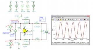
starting to work with this a bit for an article, Here, for some reason you went balanced supplies when this type of circuit works well on single supply - also, you show the input Cm loop enable at 5V using +/-2.5V supplies, also, that 1pF is way overcompensated for some reason?
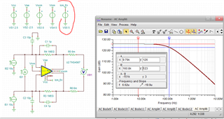
Anyway, just running my simple butterworth solution using a 11pF source C solve for a Cf=0.12pF and should give 1.8Mhz F-3dB butterworth - which looks a lot better = yes, 1.9Mhz F-3dB flat
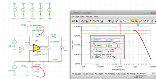
So fixing the supplies and going to the typical 0.18pF thick film R parasitic, gives this circuit - which I will use for article, those series output R's were also pretty silly, here I put in a 10MHz RC low pass. 1.16MHz now with the 0.18pF parasitic only feedback C.
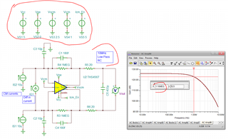
here I went a little further, testing a +/-2uA input with 50uA DC CM levels, pretty cool actually - without that input Current sink from the servo, those 50uA CM current would be taking the outputs to -50V - completely masked by the input servo.