Hi team,

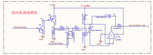
The figure above shows a circuit to control the output voltage by adjusting the PWM duty cycle.
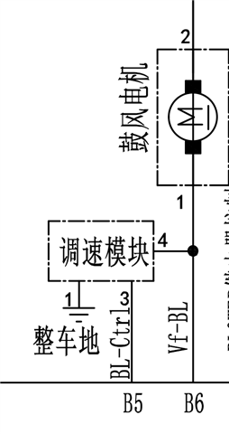
Where FTM2_blower is the PWM input, P_BAT is the fixed 12-V supply, is_FB_blower is the adjustable voltage input, and DA_blower_CTR is the adjustable voltage output. (Is_FB_blower and DA_blower_CTR correspond to the gate and drain of the MOS tube, respectively. The control diagram is shown in the figure below. The blower motor is also connected to the 12 V supply at the top. The speed control module can be simply understood as MOS tube. Is_FB_blower corresponds to VF-BL, BL_Ctrl corresponds to DA_blower_CTR)

The customer would like to know how the circuit shown above works and how the dynamic adjustment is calculated or how the static design is calculated. Thanks.
Best Regards,
Cherry


