This thread has been locked.

If you have a related question, please click the "Ask a related question" button in the top right corner. The newly created question will be automatically linked to this question.

OPA227: How to add TTL or PWM switching to control a constant current source circuit?

Part Number: OPA227
Other Parts Discussed in Thread: LM3409,

Hi Team,

If the customer want to add TTL control, what should they do?

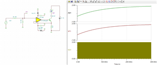
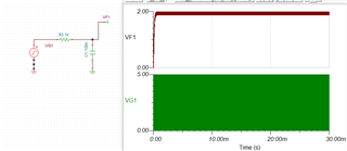
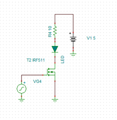
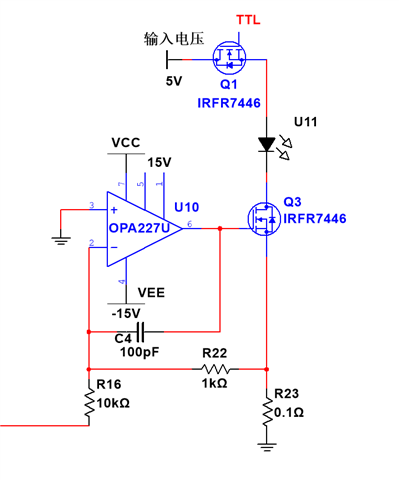
1) the preliminary preparation is shown as below, a MOS tube is connected in series. However, it was found that the TTL was 1KHz, even though it was open and closed, despite the fact that other conditions were not changed, but the average LED current dropped from 2A to below 1A (0-0.9):

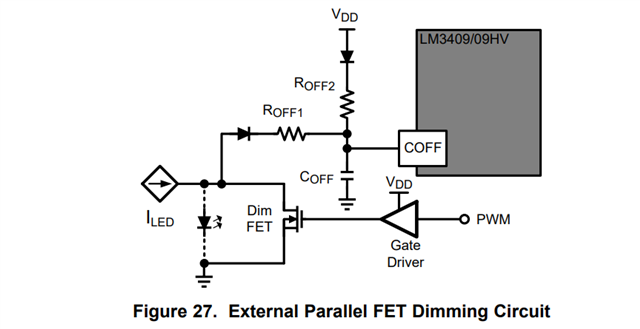
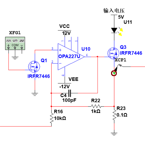
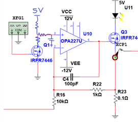
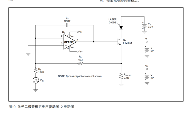
2) Then use the following method instead: 

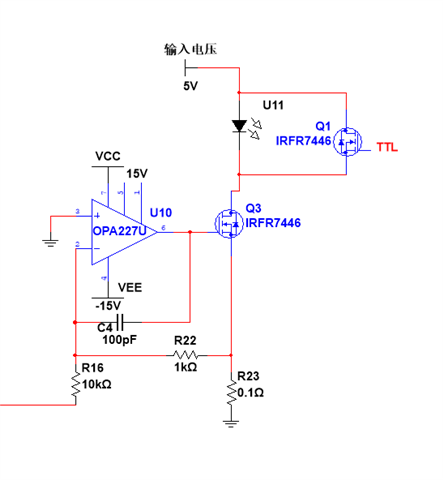
They wanted to short an LED, but it was a constant, and there was no on-off process. 

Could you help check this case? Thanks.

Best Regards,

Cherry

  • Hi Cherry,

    Unfortunately the amplifier circuit does not work well when using switched LED control circuits.  In the case above, when the current is turned "off", then the amplifier cannot regulate the voltage at the inverting input.  The output will go to the supply rail.  In this case, the amplifier is in "open loop", in this case it can take a long time to respond.

    Also, in the lower case, if the gate of the top MOSFET is set to 5 V, then the source will be a threshold below it (say, 3.5 V) - this means there will still be voltage across the LED and it will conduct.

    The only way I'm aware of to use a PWM signal to control the current through the LED in this linear circuit is to filter the PWM before it gets to the amplifier, then use the filtered PWM as the input signal. Something like this:

    Let me know if this helps.

    Regards,
    Mike

  • Hi Mike,

    Thanks for your support. As you replied, the above 2 ways are not possible.

    They've tried to put PWM directly at the amplifier input, and it was good.

    At the same time, however, the customer want to input PWM signals elsewhere for control as much as possible with the Vin input unchanged, just like the external shunt FET of the LM3409 (see figure below):

    The customer also wanted to try the following methods and passed the Multisim simulation test, not sure if it was actually possible?  The major concern here is that Vin+ floating of the OPA227 will have an effect when the MOS tube is disconnected:

    (Input voltage: 5V)

    Thanks and regards,

    Cherry

  • Hi Cherry,

    No, the schematic above won't work either.  You can't leave the OPA input high-z, which would happen when the MOS is turned off.

    Most LED switching solutions use very fast transitions between on/off, meaning the LED current is switching at a high speed (similar to the buck controller you mentioned above), and the light is effectively averaged out by the eyes. The OPA227 can't be used in the same way to quickly transition from on/off, it is not designed to do this.  You will have to create a DC voltage that the amplifier can regulate.

    But, you could add a few resistors and a capacitor, and get a similar behavior to what I proposed in the first post:

    With the additions above, the resistors to the MOS and 5V supply are used to limit the current flow.  When the MOS is OFF, current will flow from 5V to the capacitor, and when it is ON, it will flow from the capacitor to ground.  This will effectively average the DC voltage that is created by the switching on the MOS.

    Let me know if my suggestion above makes sense.  

    Regards,
    Mike

  • Hi Mike,

    But with 5 V added, Vin+ of the OPA227 produces a voltage when the MOS tube is turned off, right? And it will affect the constant current source? If this is not possible, the customer does not consider adding TTL control.

    Thanks and regards,

    Cherry

  • Hi Cherry,

    The MOSFET (note the drawing you have shown is a Metal-oxide field-effect transistor or MOSFET, which is a type of FET, but not a tube) needs a pull-up resistor, or, when it is OFF, (meaning gate voltage is LOW) then the node is floating.

    But, you really don't need the FET depending on what the driving input source is.  

    Maybe you can tell me what the input PWM source is - is it a microcontroller that is creating the PWM signal?  If so, no FET is necessary, then the PWM signal will get averaged by the R/C filter.

    See a basic example below: here, the PWM width is 40%, from 0V to 5V, at 100 kHz, so the output voltage is ~2V (40%*5V = 2 V):

    The output (VF1) can be fed into the op-amp, and is almost a DC voltage.  

    We don't recommend using the switching signal directly on the op-amp if you are trying to use it in a PWM-type of circuit.  Actually, if you only wanted to use a PWM circuit with the LED, you don't even need the amplifier, you could just use the FET connected to the LED, there would be no reason to need an amplifier:

    Do you know why the customer doesn't just want to use the circuit above?

    Regards,
    Mike

  • Hi Mike,

    Do you know why the customer doesn't just want to use the circuit above?

    Because they now want to do an LED adjustable constant current source circuit, the functions need to include: 1) output current controlled and constant current. 2) fast flashing control of LED lamps can be done by external input PWM, or TTL signals. So the circuit above was not used. 

    Thanks and regards,

    Cherry

  • Hi Cherry, 

    Let me re-direct you to one of the teams that develops LED lighting solutions, they will have more insight to the PWM solutions that are available.

    Regards,
    Mike

  • Can you give us your application requirements by filling out this a table, see below as example.

    I attached the spreadsheet for them.

    Customer Design and Help Question Sheet.xlsx:

    Once we have this information then we can do a better job what parts would work best and who should support  you.

    -fhoude

  • Hi fhoude,

    Thanks for your support and the customer will not consider to add the TTL function now.

    Best,

    Cherry