This thread has been locked.

If you have a related question, please click the "Ask a related question" button in the top right corner. The newly created question will be automatically linked to this question.

OPA855DSGEVM: Power and Resistor Value

Part Number: OPA855DSGEVM
Other Parts Discussed in Thread: OPA855, OPA859, OPA856, OPA861, TLV3603E

Hello E2E Experts,

Good day.

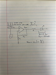
I am interested in powering a laser diode. It is a simple design, I have a clock generator that outputs +7dBm of power as a square wave. I want that to be amplified by the OPA855IDSGEVM at a frequency of 1 kHz. Then I want a series resistor at the output of the Op-amp to turn the voltage source into a current source that will be used to power the laser diode at 50mA. My question is if there is a way to add a series resistor to the output of the OPA855IDSGEVM on the board before reaching the SMA connector.

Id also like to know if +7dBm is enough to power as input into the OPA855IDSGEVM

And what the output power would be with +7dBm input so that I can calculate the series resistor I would need.

Regards,

CSC

  • Hi CSC,

    Yes there is a output series resistor on the OPA855IDSGEVM that you can use. R6 would be your best bet. 

    However a 7dBm input might be too much. 7dBm would be about 1.415Vpp, and the OPA855 is a 5V device that is decompensated and needs at least +7 V/V gain or 16.9dB, making about 9.9Vpp on the output needed on a 5V device.

    A 1kHz square wave is pretty slow I don't think you necessarily need such a high bandwidth device like the OPA855 for that, maybe consider a slower one that can handle the output voltage swing. Or you could add a resistor divider on the input of the OPA855 EVM which is possible to attenuate that 7dBm. Looks like the max output swing the OPA855 can do while staying linear is about 2.5Vpp.

    Thanks,

    Evan

  • *Unless* the dBm you are referring to is a current input not voltage. Which would be about 10mA input I believe which is doable, but with the limited voltage range on this amplifier you only need like 250ohm transimpedance gain which isn't a ton. Using this calculator and playing with the Cin to keep it stable you still get like around 600Mhz of bandwidth but it looks possible: https://e2e.ti.com/support/amplifiers-group/amplifiers/f/amplifiers-forum/956151/faq-transimpedance-amplifier-calculator

    With 2.5Vpp linear needing to drive 50mA that would be like 50ohm series on the output.

  • Hello Evan,

    Good day.

    I want to clarify the requirements needed to pulse a laser diode using the clock generator and amplifier. I am attaching a drawing of the simple Idea I have without the capacitors and the input resistor.

    My understanding is the laser diode requires 5.3V and 50mA to operate.  Here is the spec sheet if you’d like to verify. This means we need more than 5.3V on the output of the OPA885. I believe this means Vrms and not the peak-to-peak voltage. Again please correct me if I am wrong.
    The reason why id like a high-frequency amplifier is that we want very short pulses of current that will drive the laser diode and output close to single photons. The high bandwidth will allow for a sufficiently short duty cycle if my understanding is correct.
    You mentioned the OPA855 is a 5V device… Does that mean the input voltage is 5V or that you need 5V to power the device? The voltage I have measured with an oscilloscope from the signal generator is Vpp = 1.4V and Vrms = 0.5V. There are other input voltage settings available. We can range Vpp = 500mV - 3V or Vrms = 600mV - 4V. In fact, I think the goal is to tune the output current by either adjusting the input voltage with the signal generator or using a variable resistor at the output of the op-amp.
    I am a bit confused about the gain of the op-amp. If we have 7 V/V then if I input Vrms = 1V then the output should be 7V and we can use a resistor to then drop the voltage down to the operating voltage of the laser diode (5.3V).
    I don't understand the max output swing of 2.5 Vpp. Does this mean we need an input voltage that is no more than Vpp =  357mV with 7 V/V gain?
    Regards,
    CSC

  • Hi CSC,

    Thanks for your calcifications and the diagram. Yes for those small pulse widths you will need a fast amplifier, thanks for clarifying. By a 5V device I mean it only can take a 5V supply voltage (really 5.25V max) to power the device, so it can only output that much for voltage. So yes if you have a 1Vrms input signal, and the OPA855 needs at least 7V/V gain to keep it stable, then it would make 7Vrms output which isn't possible with a 5V supply. If your input signal can be 500mVpp minimum, then with 7V/V that will make 3.5Vpp output which the OPA855 won't have the output drive for either. 

    You could go with a OPA856 or OPA859 which are G=1V/V stable so you don't slam the outputs so easily.

    The 2.5Vpp *linear* output swing was a rough estimation from Figure 7-34 in the datasheet. Looks like it works linearly between about 1.25V and 3.75V on the output with a 5V supply. If you keep the output within that range you'll have the best performance. You could push it a bit further if the extra offset is ok.


    The absolute maximum output swing voltage is in the electrical characteristics table but note that this is when the output is slammed. This is still only like 2.8Vpp max, but you'll want to avoid slamming the output for these fast pulses. If you slam the device it will take some time to recover - about 3ns which would compromise the width of your pulses. 

    Hope this all makes sense.

    Either way the OPA855 won't be able to drive it like the way you drew it. That 5.3V forward voltage means at typically 50mA through the diode it will have like 5.3V across it. But there is no minimum current specified and I don't see any graphs so I'm not sure at what current exactly it turns on. 

    You *could* tie that diode to a negative voltage instead of ground and make sure you aren't slamming the amplifier. But at that point its probably better to go with a transconductance amp like the OPA861: https://www.ti.com/amplifier-circuit/special-function/transconductance-laser-drivers/products.html Should more easily convert your voltage clock to a current to drive that diode and is higher voltage.

    Thanks,

    Evan

  • Hello Evan,

    Good day.

    A follow-up inquiry.

    Is it possible to pulse width modulate the signal with circuitry on the DEM-OTA-SO? I am looking for output of a 3 ns pulse width at a 1kHz repetition rate either right before or after amplification with the OTA.

    Regards,

    CSC

  • Hi CSC,

    No the DEM-OTA-SO won't be able to pulse width modulate by itself. You might be able to use a fast comparator before the OTA to get pulse widths down to that level. Perhaps using the TLV3603E or something like that: https://www.ti.com/amplifier-circuit/comparators/products.html#83=0.000225%3B0.005& 

    Thanks,

    Evan