This thread has been locked.

If you have a related question, please click the "Ask a related question" button in the top right corner. The newly created question will be automatically linked to this question.

INA126: Possible damage to the input circuitry.

Part Number: INA126

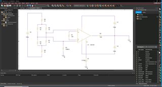
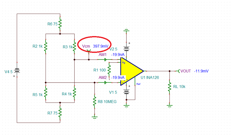
The INA126 is used the amplify the voltage difference from a strain gauge load cell. The circuit is in the attached picture. We are experiencing failures were it appears that the input stage of the INA126 is damaged. On the failed units the input resistance measures 70KOhms between pin 2 and pin 3 without any power applied. Do you see issues any with the design? Is there a better circuit topology that could used? Thanks.

  • Hi Osborne, 

    I am not aware of the issues with INA126. Do you know the failure mechanism or failure events that are taken place? Speculation would help as well. Are you able to narrow down which pins is shorten to ground or near ground? Was Pin3 or Vin+ is shorted to ground? Please provide me with additional information. 

    Based on the schematic, this is low frequency response IA gain circuit, where the BW <500Hz. 

    INA126 Strain Gauge 05152023.TSC

    Best,

    Raymond

  • Adding to Raymond's comments, it is unlikely to damage the input stage of INA126 with 1kohm input bridge unless you apply input voltages in the range of tens of volts.  The 70k input resistance between pins 2 and 3 in unpowered INA126 may simply be resistance of ESD protection diodes and thus is not indicative of any damage. Please specify what input voltage do you apply and what you see at the output that makes you think the part is damaged? 

    Please take into account that INA126 is a bipolar input instrumentation amplifier with maximum IB of +/-50nA - this means that with 10Mohm input biasing resistor the input common-mode, Vcm, may be as high as +/-1V - see below.