This thread has been locked.

If you have a related question, please click the "Ask a related question" button in the top right corner. The newly created question will be automatically linked to this question.

INA190: Designing with INA190A1QDCKRQ1

Part Number: INA190
Other Parts Discussed in Thread: INA236, INA225

Hello Team,
We are planning to use the current sense amplifier INA190A1QDCKRQ1 for one of our products.
The current can be ranging from 100nA to 1.6mA.
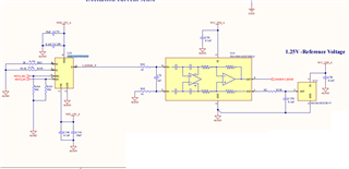
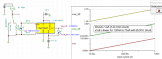
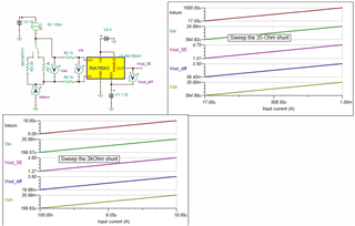
We are planning to use a 120E shunt resistor as shown in the image.


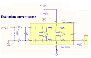
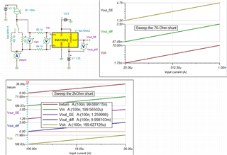
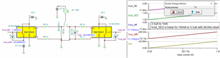
When only a 100nA is flowing through the resistor, the voltage developed across the resistor will be 100nA*120E = 12uV.
The gain of the INA190A1QDCKRQ1 is 25V/V, so the output voltage will be 300uV.

When 1mA is flowing, the voltage will be 1mA*120E = 120mV.
The output voltage will be 3V.

When only 100nA is flowing, the voltage at the input of the IC will be 12uV while the offset voltage of the IC is 15uV (Max).

1). Can I use this IC (INA190A1QDCKRQ1) for my application?
2). If not, please suggest an alternative.

Looking for your reply.


  • Hello Shibin,

    I am looking this over and will respond shortly.

    Sincerely,

    Peter

  • Hello Shibin,

    This dynamic range of current and the low starting point will probably not work with INA190. The peak-to-peak output noise can 2.5mV peak-to-peak (6 sigma), so a 300uV output shift could be buried by noise unless there is significant filtering and digital averaging.

    Additionally REF pin would need to be biased to linear voltage (~100mV) so Vout would not be in saturation during the 100nA current.

    The options are:

    1. Use two INA190s (INA190A5, 500V/V to measure for low currents and INA190A1, 25V/V to measure high currents). You could even tie their outputs together and use the ENABLE pin to turn off (makes OUT go high-Z) whichever you do not need.

    If you go this route, you may want to increase Rshunt to ~195-Ω so you can utilize the full scale range (FSR up to 5V Vs) for the INA190A1 (1mA*195Ω*25V/V = 4.88V). You could also only give the INA190A5 a REF>0V to maximize FSR for the A1, but help with saturation for the A5.

    If you can't increase Rshunt anymore, then decrease it, but replace the A1 with the A2 so that you can still maximize FSR and have Vout_A2 be closer to 5V at 1mA.

    2.Use an instrumentation amplifier and consider adjusting gain setting resistor and/or using a larger FSR/supply voltage.

    Consider looking at our analog circuits library for ideas:

    https://www.ti.com/design-resources/design-tools-simulation/analog-circuits/amplifier-circuits.html 

    Sincerely,

    Peter

  • Hello Peter,
    Thank you for your reply.
    If I am using the INA190A5 (500V/V) for the 100nA current (Shunt reistor= 195E),
    The voltage at the input of the IC is 100nA * 195E = 19.5uV.
    The input offset voltage of the IC is 15uV. 
    So I cannot use an INA190xx series. Please correct me if I am wrong.

    Can I use a current monitor like INA236 for my application?
    Is there any current monitor with adjustable gain?

    Looking forward to your reply.

  • Hey 

    Shibin, yes the offset error is comparable. But this could potentially be negated with a 1-time offset calibration protocol and this protocol becomes much easier when you are biasing the REF pin with a stable voltage and you read the differential output. You simply take one measurement of Vout-to-Vref when there is no load and VBUS and VS is on. You record this value and subtract from all reading afterwards. 

    Otherwise if your system cannot perform this protocol and take differential output measurements, then you must rely upon an amplifier with lower offset or a larger shunt resistor.

    We do have the INA225, which is a programmable gain current sense amplifier (CSA), but the input bias currents are in the uA and will not work with measuring 100nA.

    The INA236 could work, but it does have a lower differential input resistance (140 kOhm) compared to the INA190 (2.3MOhm to 4.6MOhm). See section 6.5 and Figure 6-14 of datasheet. Differential input resistance presents itself as a gain error because it creates a current divider (leakage current from the shunt). The leakage error for a 195-Ohm can be simply calculated as an additional 100*195/140,000 = 0.139% gain error.

    Sincerely,

    Peter

  • Hello Peter,
    We are planning to use an analog mux like TMUX6219DGKR.
    Please review and let us know your comments.
    The signal I_SENSE_P comes from the sensor.
    the 2K resistor and the 95.3E resistor can be selected based on the current flowing through the sensor (100nA and 1mA respectively.)

  • Hello Shibin,

    What you show could work, but you could have low signal-to-noise ratio (SNR) depending on how much filtering/averaging you can allow, see below. At 100nA, the INA190A1 will only have a 5mV differential output. Compare this to the 6-sigma 2.5mV peak-to-peak output noise. It is not great, but could possibly work.


    You could try changing to the INA190A2 or INA190A3 to increase SNR at 100nA, but then you will need to decrease the 140-Ohm to 70-Ω for INA190A2 or 36-Ω for the INA190A3. I have simulated this and you can still get measurements over the complete range (see below). I would recommend at least using the INA190A2 because it has higher input impedance (4.6MΩ) and lower input offset.


    The other option is what I mentioned where you use two different INA190s to maximize the Signal-to-noise ratio for the 100nA measurement.

      Option1.TSC

    Option1a.TSC

    Option2.TSC

    You just need to fine tune what’s best based upon your system level requirements. There could be a more optimal option where you have more overlap in the where both amplifiers are giving accurate linear measurements.

    Sincerely,

    Peter