


Part Number: OPA189
I need help understanding an odd signal I'm encountering while using two OPA189s. A simplified design is below.
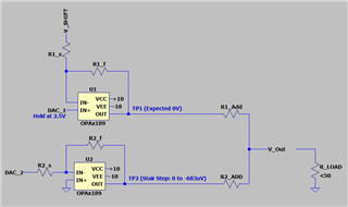
DAC_1 is held constant at 2.5V. Since U1:IN+ is at 2.5V then U1:IN+ is also 2.5V and V_SHIFT, R1_s and R1_f are such that U1:OUT is expected to be driven to 0V. This behavior is all verified in the physical circuit, but U12:OUT is 198mV instead of 0V.
DAC_2 is then stepped from 0 up to a small voltage which after the inverting amplifier puts U2:OUT from 0 to -0.683mV. These two voltages then are summed together through the current flowing through the large R_ADD resistors when a small load is attached to V_OUT. When no load is attached they create a voltage divider network with <10nA of current flowing between the two amps.
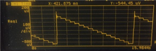
Here are the traces I'm seeing. Since the two plots were not taken at the same time, it is important to note that the highest point in both charts correspond to the same point in the waveform and that this mean the second trace is delayed from the first by one major division.
@ U2:OUT (Steps Expected, Steps Seen)
@ U1:OUT (DC Expected, Corrupted Signal Seen)
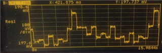
Obviously the output of the first OPA189 is being not held constant and is moving by as much as 1mV. That is more than U2:OUT is moving. U1:OUT perturbations are clearly periodic with the signal on U2:OUT but the waveform has been non-linearly corrupted. Somewhere I am missing something about how this circuit behaves. Any help here would be appreciated.

