This thread has been locked.

If you have a related question, please click the "Ask a related question" button in the top right corner. The newly created question will be automatically linked to this question.

THP210: Issues interfacing an isolated analogue amplifier with an ADC (F2837xD).

Part Number: THP210
Other Parts Discussed in Thread: INA851, AMC1300

Hello.

I am utilizing an isolated error amplifier from Skyworks which has 950kHz bandwidth. There are two problems regarding the device. Data sheet is here: Data Sheet Si8920 Isolated Amplifier for Current Shunt Measurement (skyworksinc.com).

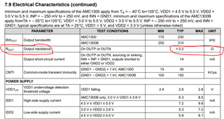
Firstly, the output impedance is 5kOhm. Although they show the device directly driving an ADC input, it is my understanding that the ADC must be driven by a low impedance source. Therefore this would not be suitable unless a large acquisition period or low sampling frequency was implemented.

Secondly, there is a common mode voltage at the output of the amplifier (page 6) of 1.1V typical. I was thinking to interface the isolated amplifier to the ADC with a fully-differential amplifier stage, as recommended in 18-Bit, 1MSPS Data Acquisition Block (DAQ) Optimized for Lowest Distortion and Noise

However, I am unsure what to set as the common mode voltage of the amplifier. It is usually set to half of the ADC reference voltage, but how do we take into account the common mode voltage at the output of the amplifier, too? 

Is it essential to have a buffering stage on the output of this Skyworks amplifier for optimal performance? My signal frequency will be anywhere from 100-300kHz. 

Best regards,

JM H. 

  • Hi JM,

    I can't give much guidance regarding your isolated amplifier as this is not a TI device. However, I can help you design a fully-differential driver for your ADC using the THP210. I would agree that with a 5kΩ output impedance, you will need an additional stage to drive the 16-bit SAR ADC.

    You are correct the output common-mode voltage of the THP210 should be set to half the ADC reference voltage. This will maximize the dynamic range of the ADC sampling. 

    The common-mode output voltage of the previous stage (common-mode input to THP210) will be rejected by the fully-differential nature of the THP210. The magnitude of the CMRR is dependent on the resistor mismatch of the THP210 external feedback network. For example, a resistor mismatch of 0.1% in a gain of 1, will result in a worst-case CMRR of -54dB (60dB typical). See section 9.1.4 of the THP210 datasheet.

    Thanks,

    Zach

  • Hi JM,

    See TINA simulation below.

    THP210_CMRR.TSC

    Thanks,

    Zach

  • Hi Zach,

    I currently don't have access to TINA on my work computer - looking to get that installed ASAP, though.

    Do you happen to have a higher resolution image of the simulation for now - it's very small on my screen.

    Would you consider the FDA approach superior to that of a standard instrumentation amplifier for driving the ADC? If so, could you please explain briefly?

    Thanks,
    JM

  • Hi JM,

    If you drag your cursor over the image it should show a magnifying glass indicator. If you then select the image it should open up a larger, higher resolution version of the image. Let me know if this doesn't work for you.

    I'm not sure I know  what you mean by "standard" instrumentation amplifier. Instrumentation amplifiers, just like normal op amps, come in both single-ended and fully-differential architectures. For example, the INA333 is a differential input to single-ended output instrumentation amplifier. Whereas the INA851 is a fully-differential instrumentation amplifier. Personally, I would consider the differential to single-ended INA to be the more "standard" architecture. If this is what you are referring to, you do not want to drive a differential ADC with a single-ended output as you lose half of your dynamic range and any common-mode errors are not rejected.

    Assuming you are referring to a fully-differential op amp such as THP210 vs a fully-differential INA such as INA851... The main benefit of the INA approach is that you have a very high-impedance input stage, 100GΩ for INA851. The input impedance of a typical FDA is determined by the input resistors chosen typically on the order of kΩ like the circuit shown in my last reply.

    Another benefit of the INA approach is that the CMRR is not dependent on external resistor matching. The CMRR is specified in the datasheet and is determined by precision matched resistor pairs that are integrated within the device. See figure 7-20 below from the INA851 datasheet.

    The FDA approach is typically chosen when the input to the FDA is low impedance, and therefore a high-impedance input stage is not required.

    I believe your original concern was that the output impedance of your isolation amplifier is too high and therefore will perform poorly. I used the TI cross reference tool (https://www.ti.com/cross-reference-search) to see if there is an alternative device with better performance. I was able to find the AMC1300 which has a very low output impedance of ~0.2Ω, see below. The 1ku pricing on ti.com looks quite good as well: https://www.ti.com/product/AMC1300.

    Thanks,

    Zach