This thread has been locked.

If you have a related question, please click the "Ask a related question" button in the top right corner. The newly created question will be automatically linked to this question.

VCA2617: VCA2617RHBT

Part Number: VCA2617


We are using a variable gain amplifier from TI (Model No:  VCA2617RHBT ) and observing high settling time.

We had made the following observations.

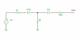
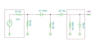
With 440 uF decoupling capacitors gave a settling time of ~15 minutes.

With 220 uF decoupling capacitors gave a settling time of ~10 minutes.

With 4.7 uF decoupling capacitors gave a settling time of ~2 minutes.

With 100 nF decoupling capacitors gave a settling time of ~<1 minutes.

We need to use the 440uF capacitors in the circuit for other reasons.

But settling time of ~ 15 mins is the issue. 

Looking forward to support / resolution.

  • Hi, 

    1. Can you specify where you have the decoupling capacitor with a block diagram? Is it on supply, input, bias-pin, common-mode pin? 

    2. Can you explain how you are measuring the settling time?

    3. What is your application? 

    Thanks, 

    Karthik

  • Hi Karthik

    Pls find the responses to the queries below: 

    1. Can you specify where you have the decoupling capacitor with a block diagram? Is it on supply, input, bias-pin, common-mode pin?

    The bypass capacitors are on the input side as shown in the block diagram. Have put additional decoupling capacitors for supply, bias-pin and common-mode pin.

    1. Can you explain how you are measuring the settling time?

    So, keeping the gain constant, for an input signal, we expect a corresponding output signal with gain. We’re measuring the time it takes for the output signal to stabilize (measuring with oscilloscope).

    1. What is your application? 

    Ours is a fiber sensing based application. 

    Looking forward to quick support and resolution.

    Regards,

    Nagaraju

  • Hi Ashit, 

    This is possible. The input resistance of the device is 300k-ohm. 

    5*time constant (for a 1% settling) with 400-uF is 11 minutes. 

    Why do you need such a high capacitor for your application?

    Can you not have a network like below? Then, the time constants will be less than 100ms. 

    Thanks, 

    Karthik 

  • Hi Karthik,

    Please find the response below: 

    • We required high capacitors in our application to pass through very low frequency signals (~ 1 HZ).
    • In the network you had suggested, it looks like there is again a 10 nF capacitor in chain, won’t this increase the lower cut-off frequency to a very high frequency value?

    Regards,

    Nagaraju

  • Hi Ashith, 

    How about this network? 

    R1 is source resistance which I have matched on the board with R4. If your source resistance is different, then change R4 accordingly. 

    R3 and C3 are device's internal impedance. 

    Frequency response from VG1 to VF1 is in the plot below. The gain is flat at 1Hz and -3dB bandwidth is 65.54mHz. 

    To analyze the time constant for this network i) focus on the discharge of C1 which is in the red loop: 5 x 470uF x 10k-ohm = ~25ms, ii) focus on the discharge of C2 which is the blue loop: 5 x 10uF x 300k-ohm = ~15s. So, the dominant time constant between the two is from loop 2 which is about 15s which should be sufficient for your application.  

    Thanks, 

    Karthik