This thread has been locked.

If you have a related question, please click the "Ask a related question" button in the top right corner. The newly created question will be automatically linked to this question.

OPA549-HIREL: Thermal shutdown in bipolar supply config. for one direction of output state

Part Number: OPA549-HIREL
Other Parts Discussed in Thread: OPA549

Hello,

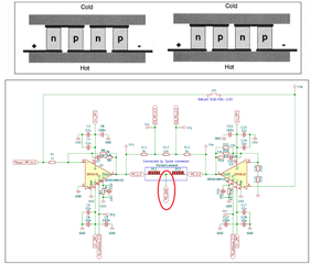
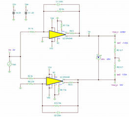
I am trying to develop a power stage for two peltier elements. The circuit is the following:

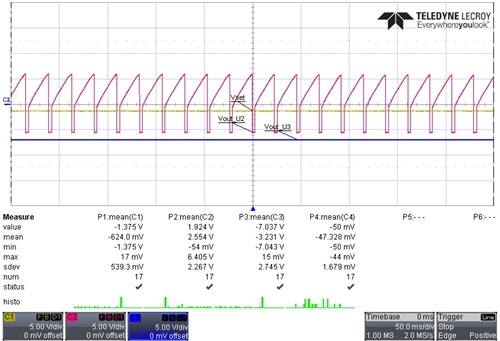
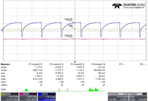
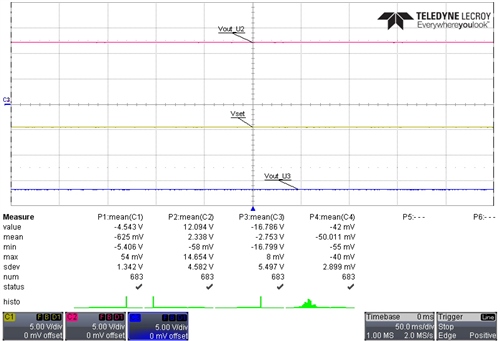
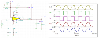
The circuit was adjusted to 3.2 A current limit (R7 and R17) and low pass filtered (C7 and R8, C14 and R14) to 4 Hz. When the set voltage is for example +2.5 V and the output of the amp U2 is set to -10V (+10V U3) which leads to a current of around 3.2 A the amp with the negative output voltage is fine (U2) and the one with a positive voltage is going into thermal shutdown (U3; freq. is around 30Hz). If now the set voltage is adjusted to -2.5 U2 goes in thermal shutdown and U3 is fine. For testing if it is a thermal problem JP1 was removed and only U2 was supplied by +- 20V and the output set to -10V (@3.2A) --> no thermal shutdown. Before the first prototype was build the T_J was calculated for the worst case: T_J = 25°C + 37.5 W * 0,9°C/W (acc. thermal resistances) = 58.75°C which should be fine. To be sure the thermal resistances were practically measured: case to heat sink 0.47 K/W, heat sink to another heat sink 0.33 K/W, junction to case 0.1 K/W which leads to the theoretically calculated 0.9 K/W. As long as the output voltages of the opamp is negative it is fine, when it's positive the problem occurs. Thermally it should be fine. Any suggestions to fix this?

Kind regards,

HD

  • Hi HD, 

    if it is a thermal problem JP1 was removed and only U2 was supplied by +- 20V and the output set to -10V (@3.2A) --> no thermal shutdown.

    This configuration implies that that the circuit has no thermal shutdown issues (by opening JP1). When JP1 is shorted, it seems that it completes a current loop or some kind. 

    Please try the following: disconnect the PE-GND circled in red and shorted JP1, and see what it will do. My guess is that there will be no thermal shutdown. Please try that and see what is the outcome. I have a feeling that drivers are shorted to something through the peltier coolers.  


    Best,

    Raymond

  • Hello Raymond,

    I disconnected the GND in the middle of the TECs (makes no difference with or without). @ +-18.5V supply voltage still the same:

    Red output voltage U2
    Blue output voltage U3
    Yellow set voltage (Power_PP_in.2)

    Negative set voltage

    Positive set voltage

    As you can see only the OPAMP which has a positive output voltage runs into that problem (whether it's an inverting or a non-inverting amplifier). One thought was if we have a mosfet output stage and one mosfet is directly connected to the metal tab (V-) and the other is electrical isolated connected, do both sides have the same thermal resistance of 0.1 K/W from the data sheet (is this value the worst case)?

    Kind regards,

    HD

  • Hello Raymond,

    I did on more test. When replacing the TECs by 9.7 Ohms (same resistance like the TECs) the instability is gone (without GND tested). But if the amplifier are in the current limit you can see an offset:

    Offset current limit

    Maybe this is due to a too small supply voltage. But how I could get the amplifiers stable? In the classic application notes a resistor would be placed in series to the TECs (to drive capacitive loads), but this would generate a lot of heat and unnecessary power consumption.

    Kind regards,

    HD

  • Two snubbers with 10 Ohms and 10 nF at the outputs of the opamps can't fix the problem too.

  • Hi HD, 

    In the classic application notes a resistor would be placed in series to the TECs (to drive capacitive loads), but this would generate a lot of heat and unnecessary power consumption.

    You are correct that this may be resulted from the oscillation due to the capacitance of TEC. Could you measure the TEC with LCR meter and provide me with these figures? We need to do a loop compensation for the driver. 

    With resistor in series with TEC, it is an easy way to get compensate the pole generated from OPA549's Zo impedance and TEC capacitance. By addition a resistor, Riso in the middle (or in series with the TEC), the circuit creates a zero to compensate the pole. Depending on the TEC capacitance, the value of Riso may not need to be very large. 

    If you provide me with LCR value, I will figure it out the best driving configuration. Also, I did not see the TEC temperature control loop. Can you tell me what is bandwidth of the temperature control loop? Is it below 100Hz?

    OPA549 TEC 01192023.TSC

    Best,

    Raymond

  • Hi Raymond,

    here are some bode plots of the load:

    Two TECs in series cold:

    One TEC cold:

    The current limiting resistor should be something like 16k for 3.2A. What's a little bit weird, that the opamps are only unstable in a specific load situation. Maybe we do a pole compensation/adjustment but would this be valid for all load situations? A BW of something around 10 Hz would be sufficient (LP of fc=10 Hz in front). Thank you for providing the simulation.

    Kind regards,

    HD

  • Hello Raymond,

    I did some further investigations. When I connect two high power resistors with 2 Ohms instead of the TECs the problem is still present. So the problem seems to be not frequency depended. If I double the resistance to 4 Ohms (8 Ohms) everything is fine. If I connect two TECs in series to only one amplifier side it works fine with +-20V supply voltage and 3.2 A current limit. Why the positive rail has a problem with a two Ohm resistive load (no capacitance or inductance)?

    Kind regards,

    HD

  • Hi HD, 

    The non-inverting side needs to be bandwidth limited with approx 330nf capacitor. Without it, the simulation indicated that it has over 92 degree of phase margin. 

    When the non-inverting input side is bandwidth limited, say approx. 48Hz (10kΩ||330nf), it has 360 - 274 = 86 degree of phase margin. 

    OPA549 TEC AC Analysis bottom 05262023.TSC

    Below is the small signal transient response, it seems to be stable without overshoot. 

    Please adjust your compensation parameters per the simulation and see if you have additional issues. I know that I limited the BW significantly. Since this is TEC and temperature control application, it is not required to have the high BW response time anyway. The thermal response within the TEC is a significantly slower than 10Hz or 100Hz. 

    Best,

    Raymond

  • Hello Raymond,

    I already limited the BW of around 5Hz and it is still unstable (also I increased the amplification). I will play a little bit with the simulation, but I think without a series resistor it can't be solved.

    Best,

    HD

  • Hi HD, 

    In your previous impedance vs. frequency measurement, the phase is negative (-25degee or so). That means that the TEC has some capacitance. If it is all resistive, it should have zero phase shift. So I estimated that the TEC is in an order of 33uF at 100Hz. I do not know why that is not seen in impedance plot, which is a straight impedance responses up to 10kHz range. 

    Assume that TEC has 22uF capacitive load, this may be the TEC driver you need for the application. I am not promising that this will resolve your issues, but it should be close. There are large capacitive characteristics in TEC, which is more than what I thought. If the capacitive load is such large, placing a capacitor with FB resistor by limiting the bandwidth may not work

    Here is the AC analysis for the 22uf capacitive load. Check if it works better or oscillate less than before. Also could you verify the capacitive characteristics of the TEC? 

    OPA549 Peltier Cool Dual FB 05302023.TSC

    Please let me know if you have additional questions. 

    Best,

    Raymond

  • Hi HD, 

    Please let us know if your issues have been resolved. I was not sure that if the previous compensated power amplifier is enough to stabilize the capacitive load of TEC. 

    Best,

    Raymond

  • Hi HD, 

    I am going to close this inquiry.

    If you have additional questions, please let me know. 

    Best,

    Raymond