A related question is a question created from another question. When the related question is created, it will be automatically linked to the original question.
If you have a related question, please click the "Ask a related question" button in the top right corner. The newly created question will be automatically linked to this question.
The most common causes of op amp instability is load capacitance connected at the amplifier output, or input capacitance in the inverting terminal. Both capacitance at the op-amp input (inverting terminal) and output capacitance are often the culprits of unstable op amp circuits when the circuit is not properly compensated.
In the diagram on your post above, the amplifier sees a load of (30kΩ || 0.1uF) in series with 10kΩ resistor, and as it is shown on the simplified diagram above, without any additional load capacitance, the amplifier is stable since there is a relatively large series10kΩ resistor in the path. What circuit or what load is connected to the output of the op-amp?
Best practice is to perform a detailed stability analysis and check the circuit for proper phase margin accounting both for the feedback components and any additional load connected at the output of the amplifier. If you require assistance determining the stability or compensation of a op-amp circuit, please provide a complete schematic showing the feedback components, and the load that is connected to the output of the op-amp.
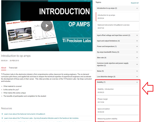
Op-Amp stability is an extensive subject, below is a link to the TI Precision Labs, Op-amp Tutorial Videos. The stability session contains 7 videos.
It is always best to provide a complete/detailed schematic, since it is difficult to interpret the exact circuit configuration with words.
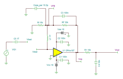
For example, assuming this is the correct circuit, in the non-inverting configuration:
In the above, the amplifier is driving an RC filter with R=10kΩ and C=10nF. The relatively large series Riso resistor helps making the circuit stable, while driving the 10nF load capacitance. Below is the Open-Loop Stability analysis, showing 74-degrees of phase margin.