This thread has been locked.

If you have a related question, please click the "Ask a related question" button in the top right corner. The newly created question will be automatically linked to this question.

OPA810: How to improve amplifer circuit noise

Part Number: OPA810
Other Parts Discussed in Thread: THS4551, , TINA-TI

Hello,

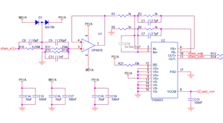
Please see below issue. We located the root cause is from amplifier circuit.

I would like to ask how to calculate the noise based on current power design.

How to improve this issue?

ADC3422: adc3422 output data issue - Data converters forum - Data converters - TI E2E support forums

  • Hello Liping,

      I went through the ADC e2e discussion. We can simulate the OPA810 + THS4551 design in Tina-TI to estimate the total output noise. First, to clarify, it looks like you tested the ADC without the amplifiers connected via removing resistors R12 and R14 (and other resistors for other channels to the ADC) and the improvement was for only one of the channels. For the other 4 channels, is the amplifier schematic the same? Can you provide a large enough input to the OPA810 and probe at the output of the OPA810 and at the output of the THS4551 and confirm the correct output voltages without the ADC connection? 

       Also Ikram's suggestion on sharing the power supply schematic would be helpful as well.

    Thank you,

    Sima 

  • 1) 4 channesl schematic are the same.

    2) wiht large input such as 12V, the OPA810 and THS4551 works fine. Based on multimeter & oscillscope measurement.

    3) power supply schematic, see attachment.

    1033.schematic.pdf

  • Hello Liping,

      Thank you for the confirmation. Your supply filtering is sufficient, but if looking for an upgraded version, a pi filter is best for high frequency noise, for isolating the supply voltage from the current changes of other amplifiers, and reducing noise into the ground plane. 

       I will set-up the simulation in Tina-TI and get back to you on noise performance of your amplifier front-end. 

    Best Regards,
    Sima

  • 1) add one 100nF parallel with amplifier VOCM C13, no improvement

    2) add one 10uF parallel with amplifier VOCM C13, no improvement

    3) add one 10uFparallel with amplifier 5V power supply C18, no improvement

    4) install 2.7pF on C10, big improvement.

  • Hi Liping, 

    Sima is on vacation this week, so I will continue to help. From your previous results where installing 2.7pF on C10 made a significant improvement, can you share what the difference was in the noise before and after? 

    Thank you, 

    Jacob 

  • Before add C10, the peak to peak count is 40.

    After add C10, the peak to peak count reduced to 10.

    Do you know why from circuit simulation and analysis?

    Where does the noise comes from?

    Should be any issue in layout?

  • Hi Liping, 

    C10 should not reduce the noise, but it could potentially help if there was an oscillation. However an oscillation seems unlikely in your current configuration unless you had a lot of additional capacitance from the PCB. 

    Another possibility is that it is providing a 30 MHz filter on the input. Is there a possibility that you might be coupling in eletromagnetic interference or have wideband noise from the previous stage? 

    Regards, 

    Jacob 

  • So Liping, adding that 10pF across the FDA inputs is shaping the noise gain up at higher frequency. that indicates that you were margininally stable before you did that. hence, a LG phase margin sim would be useful where the exact THS4551 load would be needed.