This thread has been locked.

If you have a related question, please click the "Ask a related question" button in the top right corner. The newly created question will be automatically linked to this question.

OPA855: 27 MHz Differential Amplifier with OPA855

Part Number: OPA855

Hi everyone, 

I am looking for some assistance on an amplifier circuit used to sense a current at 27 MHz.  Some of the spec's I am looking for in the circuit:

Power supply: 3.3 Vdc, single sided,

-30 mV <  Vdiff < +30 mV

-1 V < Vcm < +22 V

Desired Gain:  > 20 V/V

Because of the high frequency and potentially high common-mode voltage, I could not simple current sensing amp (one of the INAxxx devices, for example).   I choose to make a difference amp using the OPA855  and am looking to get the maximum voltage swing out of it (if I need more gain I can add another stage).  However, I cannot get the amplifier to work, at least in LTSpice, with my circuit, shown below:

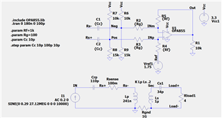
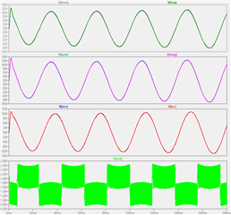
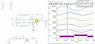
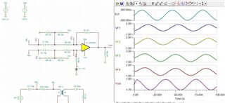
I thought I could DC bias the inputs to the middle of the acceptable Vcm range (~2.0 VDC) and couple the high-frequency differential in.   I then add a Vref to set the output common-mode voltage to the middle of the output swing range (1.15-2.35 V, so set Vref to 1.75 VDC in the above circuit).  However, I am not getting the expected output.    First, even with just a 10 pF of coupling capacitance, the Vcm at the input pins seem to stray way out of range and the output looks horrible.  I am trying figure what's going on but am at a loss.   Can anyone comment if I am missing something?  Any thoughts would be appreciated!

Thanks

John

  • FYI - I think I may be hitting an input offset voltage issue, but am not sure.

  • Hello John,

     From the sims, it looks like there is some instability and hitting the output voltage violation of the device. This is most likely do to the combination of the DC bias set at the input + Vref. I will recreate the issue in our simulation software, and update you on the solution. 

    Thank you,
    Sima 

  • Hi John, Apologies for the delay. Sima was on vacation and will get back to you tomorrow. 

    Best, 

    Jacob 

  • Hello John,

      Sorry for the delay on this issue. I have been working on the sim the past day, and will be able to update you with the solution before end of the week.

    Thank you,
    Sima 

  • Hello John,

      Thank you very much for your patience here. I was able to replicate your sim and issue on our end:

       Looking at the inputs of the transient analysis, there is a input voltage violation of the device. That is the reason the CMRR is very low. For a CMRR > 80dB at 3.3V, the input voltage must be within 1.1V to 2.9V. 

       A quick fix would be to adjust the sense resistor + total impedance seen by current source:

      There seems to be a slight time/phase delay, but that can be tuned by the input RC. Let me know if you have questions on tuning for Vdiff + desired output voltage range. 

    Thank you,

    Sima 

  • Hi Sima, 

    Unfortunately I cannot change the circuit in the manner that you did, by increasing the value of C4.   I am thinking that I could just decrease the values of the capacitors C1 and C2 that couple the AC signal to the amplifier circuit to a point where the input voltage does not exceed the 1.1V to 2.9V.  Any thoughts on how I could change the sensing amplifier circuit without changing the circuit it is sensing from?

    But I first have to ask why your DC biasing resistor dividers are 9.15k & 8.10k on the non-inverting pin but 7.15k & 6.10k on the inverting pin?  Is this to compensate for the input offset/biasing current?

  • Oops, disregard my question about the bias resistors.   I misread the image - the grid dot looked like a decimal point to me!  :-)

    So any ideas on how to decrease the voltage without changing the circuit being sense would be appreciated.

  • Sima, 

    I can make the input voltages meet the 1.1V to 2.9V range by dividing down the signals, but I lose my differential voltage as well.   Looks like I may need a different amplifier device, one with a higher Vcm input range.    Given the application, any suggestions as to what device may work best for me?

    Thanks

    John

  • Hello John,

      When you mentioned values of C1 and C2, I went ahead and checked AC response of the circuit, and it looks like it could use some fixing/tuning. I am working on this, and would be able to send an updated circuit by end of the week. 

       For dividing down the signal, wouldn't the differential be the same if both signals are divided consistently

    Thank you,

    Sima