This thread has been locked.

If you have a related question, please click the "Ask a related question" button in the top right corner. The newly created question will be automatically linked to this question.

INA128: Output clamped below 1V

Part Number: INA128

Hi Team, seeking some inputs for a customer.

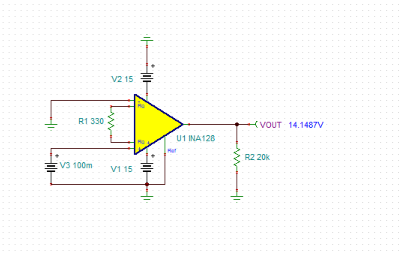
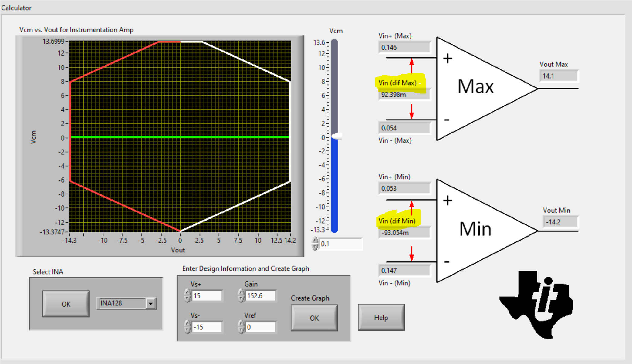
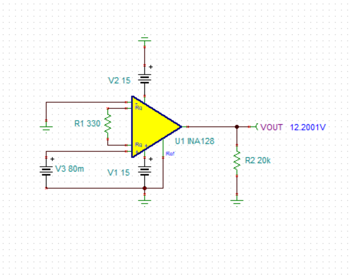
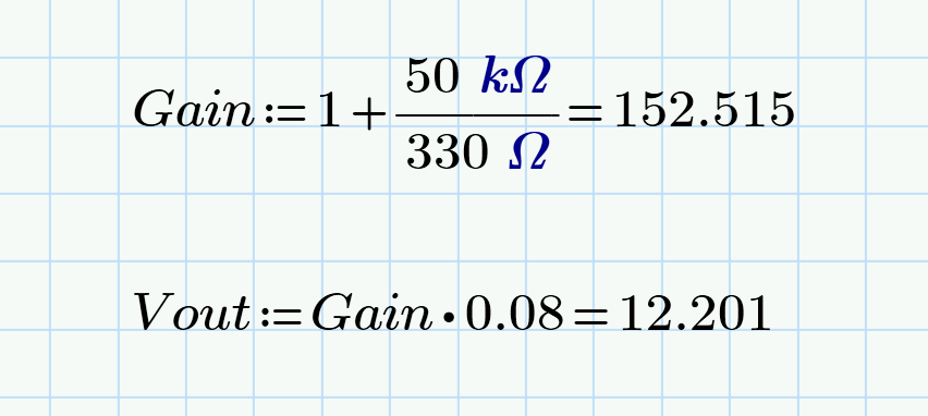
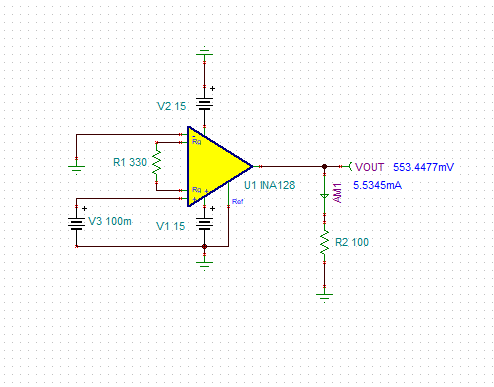
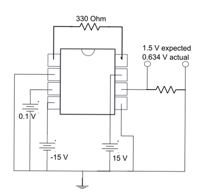
Working with an INA128 chip and I've noticed that it's output voltage seems to be capped at 0.634 V, despite my testing expecting higher outputs, is this a result of a dead InAmp or is there another issue?

Thank you for your time.

_______

Thank you.

-Mark

  • Hey Mark, 

    Simulating this shows that the amplifier rails out in this configuration. 

    Looking at the Analog Engineers calculator (link below) and input the conditions for supply, reference, gain and common mode voltage you can see the input differential min and max. Note that the max differential voltage in this configuration is 92.4 mV. 

    https://www.ti.com/tool/ANALOG-ENGINEER-CALC

    Bringing the differential voltage into the linear operating range, the device no longer rails out. 

    Using the gain equation and checking the expected gain I get an output voltage of 12.2 V which aligns with the Tina simulation. 

    Let me know if I can be of further assistance on your circuit. 

    INA128.TSC

    Best Regards, 

    Chris Featherstone

  • Hi Chris, 

    Thank you for your response. Please see the feedback from our customer.

    "I want to be absolutely clear - the suggestion and explanation you gave were patently incorrect. A 1V input bias with 1x gain was railing out in my configuration, which your calculator, gain equation, and all other documentation says should never rail out.

    However, I managed to get it from the screenshot you sent me. I believe the issue is that I was using a 100 Ohm test resistor, while your screenshot shows a 100k test resistor. Testing in TINA, I do see that a 100 Ohm test resistor does not properly rail out at 14.2 V like it does in your screenshot, matching my testing.
    However, I do not understand why this is. Is this to do with the output current of the in-amp being limited in what it can provide? If you could help me understand, I'd appreciate it."

    Thank you for extending your support. Your help is much appreciated.

    Kind regards, 

    Marvin

  • Hello, 

    Thank you for the additional information on the output resistor value. If the output resistor is 100 ohms, the amplifier is entering current limit. The most output current the device can provide is 6 mA sourcing. My prior simulation assumed a light load or 20 kohm output resistance. The amplifier rails out in this condition. As the amplifier sees a heavier load such as the 100 ohm resistor, the output voltage starts to sag and this is the reason for the 0.634V seen on the measurement or the 0.533 mV seen in Tina below. 

    If you remove the 100 ohm resistor on the output, does the amplifier rail out to approximately 14V?

    Figure 1-13 shows the output voltage sag the more output current the INA has to provide. Eventually once the output is 0V the device is in short current limit and approximately 6 mA would be the most it could deliver. 

    I hope this helps. Let me know if I can be of further assistance. 

    Best Regards, 

    Chris Featherstone