This thread has been locked.

If you have a related question, please click the "Ask a related question" button in the top right corner. The newly created question will be automatically linked to this question.

LM7321: LM7321MFE/NOPB op amp not (or suddenly stops) working.

Part Number: LM7321
Other Parts Discussed in Thread: TLV2374, OPA4991, LM8261, TLV2371, OPA2991, OPA4353, OPA991

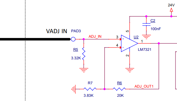
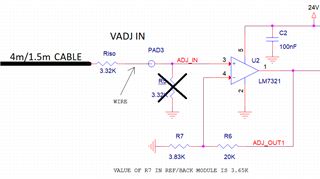
We have a design of the leds driver. 

Part of this board responsible for leds intensity circuit shown on the upper side of the attached diagram.

Intensity control (adjust voltage) is connected from another D/A board through a cable (with up to 4 meters length). Adjust (intensity voltage) is 0VDC-3VDC. This board is shown on the bottom side of the diagram.

Sometimes we encounter a problem with LM7321MFE/NOPB (U2) op amp: it simply not (or stop) working.

We can measure 3VDC on PAD3 but around 0-0.2V on U2/1 (or R6). And of course, the same low voltage on PAD4. The amplifier does not seem to be burned and soldered ok with all relevant components but simply not amplifying input voltage.

I don't have a failures percentage, but the problem is very disturbing as it can occur from the beginning after assembly or suddenly after some time of good working or from the beginning

Can you advise us what could be the problem and what should be done by us?

Thank you.LedsIntensityControl.pdf

  • What is the output load? Can you check if the output (when working) is oscillating?
  • Hello

    The output load is another LM7321MFE/NOPB op amp as shown in diagram - U3 (unity gain amplifier).

    Thank you

    Alex 

  • Hey Alex

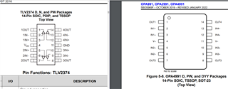
    A 4m cable can be a significant capacitive load. Tlv2374 is not designed to drive large cap loads like the lm7321.

     That is your most likely point for instability.

     Unfortunately without a footprint to add a series resistor to isolate the capacitive load, or a gain resistor to change the gain your option for a BOM level change is to change the op amp, which changed many other parameters in your design.

     Best,
     Jerry

  • Hello

    So, you think that the capacitive load caused to the oscillations at the input of LM7321 and to the constant damage of LM7321?

    The voltage level set by D/A to the cable is not frequently changing (actually in more than 99% only on power ON/OFF). 

    If we will add a series resistor:

    1. What value of resistor you recommend?

    2. Where to add the resistor - at what side of the cable?

    We can consider also to replace TLV2374IDG4 op amp.

    3. Do you have an alternative one that suitable for us and have the same footprint?

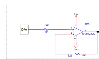
    Actually, the full schematics of the TLV2374IDG4 is as follows:

    In my diagram I showed only a connected - assembled components.

    4. I can add some resistors on R21 and R23 - can something like that help to solve this issue? 

    Thank you very much.

    Alex

  • Hey Alex,

    Even if the signal is not changing, if the circuit is unstable it can still oscillate. This may or may not damage the LM7321 depending on the supply voltages and output voltage of the TLV2374. In any case, it will at least make the output unpredictable.

    The simplest fix to design for this is a series isolation resistor on the output of the amplifier. This will be placed before the cable close to the output pin of the amplifier. Typically only a small value is needed, and the larger value you add, the more DC error you can introduce.

    The simplest BOM change is to add some gain to the TLV2374 until the output is stable, then scale down your DAC output accordingly. In this case, I'm assuming Ref is Gnd.

    100 Ohms and a Gain of 10 are examples chosen randomly. The amount of isolation resistance or gain you would need depends on the cable capacitance, and will vary amplifier to amplifier.

    You can assess the stability of the circuit by probing the output of the amplifier (before the isolation resistor if you use one) and measure the output response to a small signal step on the input (small signal is <100mV) 

    The last resort to fix this is to change the amplifier. This is the last resort because you change so many other variables when you change the amplifier.

    Best,
    Jerry

  • Hello

    What do you think if I will replace an existing TLV2374 with OPA4991IDR. It is the same package (footprint device) with better capacitive load driving?

    I understand that I still need to insert an isolation resistor. Without changing the layout of the PCB I can solder it inside the cable near the output of the op amp. What you think about it? What value of resistor I need?

    Regarding the gain - I prefer to work in an unity gain configuration (as otherwise an application side change will be required for D/A's scaling down).

    Also, I noticed that currently in the BOM we have a 10K resistors in R20 and R22.


    Is it better to change it to 0 ohm values for an unity gain?

    Thank you

    Alex

  • Hi Alex,

    What do you think if I will replace an existing TLV2374 with OPA4991IDR. It is the same package (footprint device) with better capacitive load driving?

    It might help but I would make sure to run some stability simulations on both the TLV2374 and the OPA4991 to ensure that moving to the OPA4991 would be a better choice. You can see how to run stability simulations in our videos going over stability here.

    I understand that I still need to insert an isolation resistor. Without changing the layout of the PCB I can solder it inside the cable near the output of the op amp. What you think about it? What value of resistor I need?

    A good starting point would be to look at a 100ohm resistor and simulate with the expected parasitic capacitance if that helps it. If you still see stability issues, then increase the resistor value.

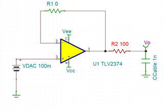
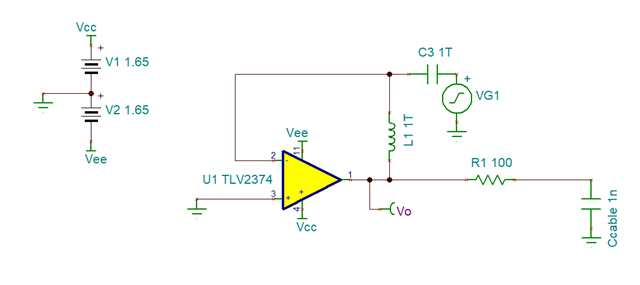
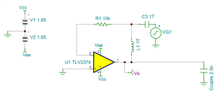
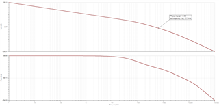
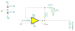
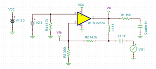
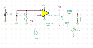
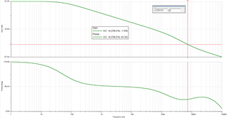
    For example if I was to assume that the parasitic capacitance is 1nF (I'm not entirely sure if that's true in your case), I would build the following circuit: 

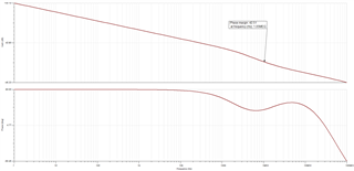
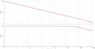
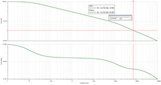
    From the results you can see the phase margin is 42.5 degrees. That's near the recommended minimum of 45 degree phase margin that we try to have, so increasing the Riso resistor slightly would further help stability of the circuit. I recommend taking a look at the stability videos to better understand how this circuit works. 

    The trade off of using an Riso is there will be some drop on the output voltage going to the LM7321. That's why we say the starting point is recommended to be at 100ohms to minimize the voltage drop effects while still improving the stability. 

    Also, I noticed that currently in the BOM we have a 10K resistors in R20 and R22.


    Is it better to change it to 0 ohm values for an unity gain?

    R22 gives some isolation and current limiting between the input of the op amp and the output of the D/A. R20 is acting only in isolating the inverting input. There shouldn't be any need for this. 

    Best Regards,

    Robert Clifton 

  • Hello

    With TLV2374 we need to make experiments in the LAB (and practice from the field) to verify that we have a good solution to the problem that can appear not very often. 

    As we want to get a fast and most robust solution: If anyway TLV2374 is not a good component to drive capacitive loads we prefer to modify PCB layout of the driving circuit and to use a better component.

    I see that LM7321 (that we have already in a receiver side of the cable) is designed for driving unlimited capacitive loads without oscillations. 

    What you think about: if we will modify a PCB layout and place LM7321 between D/A and 4 meters length cable instead of TLV2374?

    Or there any other solution like placing specific buffer before the cable and etc..

    Thank you

    Alex

  • Hi Alex,

    The LM7321 does have the unique unlimited capacitive load architecture that allows for better stability while driving a capacitive load. I thought it would be challenging to replace a quad channel device, like the TLV2374, with a single channel LM7321. But if you were using the TLV2371 in a SOT-23 (DBV) package, then LM7321 and LM8261 would be good alternatives. 

    Do you know know what the parasitic capacitance of the cable is expected to be? 

    Best Regards, 

    Robert Clifton

  • Hello Robert

    I am still trying to figure out the capacitance value we have (it is not mentioned in 4meter's cable's datasheet) and I am waiting for manufacturer's answer.

    Actually, there are 3 cables connected in series: 2 very short: totally with length of ~40cm and probably total capacitance value of ~60pF and 4 meters cable (with currently unknown capacitance).

    Regarding the R20 and R22 resistors that you wrote I don't need. 

    Is it possible that for example that R20 resistor with 10K value (instead of 0 value for unity gain) can actually affect on op-amp stability issues by combining RC filter between this resistor and input capacitance of the TLV2374 op-amp?

     Thank you.

    Alex 

  • Hi Alex,

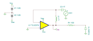
    Yes, having R20 can cause stability issues. Here's my simulations showing the difference:

    Without R20: 

    versus with R20 10k. 

    I see a difference in about 20 degrees of phase margin degradation. Removing it will help. Same holds true without the Riso resistor but the phase margin is much lower. 

    Best Regards,

    Robert Clifton 

  • Robert 

    And what about R22 resistor with 10K value between D/A and positive input of the op amp?

    Is the proposed value of 0 ohm can also to contribute to the stability?

    Thank you very much.

    Alex

  • Alex,

    R22 will not contribute to the overall stability of the op amp since it's not part of the feedback path. 

    I recommend making R20 0ohms. 

    Best Regards,

    Robert Clifton

  • Hello

    Finally received a response from one of the cable's manufacturers it is 140nF/km.

    So, I think we will have ~620pF capacitance for 4 meters cable + additional cables connected.

    Still waiting for capacitance value of an alternative cable we use (maybe it worst).

    What you think?

    Thank you very much.

    Alex

  • Hi Alex,

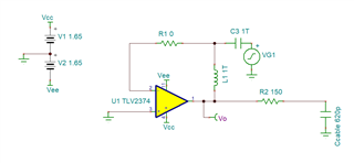
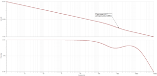
    You will still see stability issues in the circuit. I saw about 14 degrees of phase margin without any Riso.

    Versus going in with a Riso = 150ohms you get a phase margin of 48 degrees. 

    Best Regards,

    Robert Clifton 

  • Hello

    Now we get an answer from another cable manufacturer.

    According, this answer we have a capacitance of around 2500 pF !!!!

    What do you think?

    Thank you

    Alex

  • Hi Alex,

    Well from my simulations, this would be even more problematic than what we original calculated. 

    This will require adjusting the Riso value. I'll get back to you in a bit with the adjusted Riso value needed. 

    Best Regards,

    Robert Clifton 

  • Hi Alex,

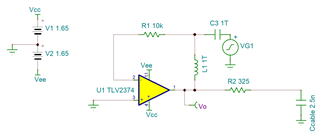
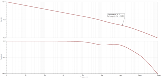
    I ran the Riso calculations and got a value of about 325ohms to give a phase margin of 54.17.

    Best Regards,

    Robert Clifton 

  • Hello Robert.

    1. As I see you performed a simulation with 10K resistor in the feedback path. As we saw before this value contributes to the instability issue, and it will be better to have 0 ohm resistor.

    2.Can you please run a simulations also with TLV2374 and LM7321.

    Thank you very much for your help.

    Alex

  • Hi Alex,

    Thanks for catching that! I highly recommend taking a look at how to run an op amp stability analysis located here, so that you don't have to wait for me to run this. 

    I took a look into the models of both TLV2374 and LM7321. Both of these models are very old and didn't properly model the output impedance of either device. That means that whatever data you get from the simulations might not be entirely accurate in the values but could still provide some useful information. 

    So taking a look at the difference of the TLV2374 with and without an Riso, while maybe not giving accurate values, will still show what can be done to improve the stability of the op amp. 

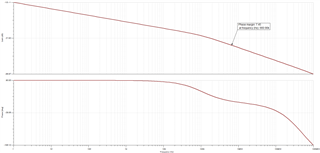
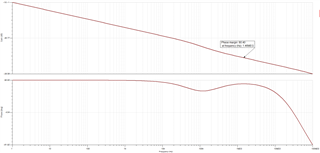
    Without Riso: phase margin is 7.45 degrees. Very unstable. 

    With Riso: Phase margin is now 80 degrees. Stable. 

    The LM7321 has an added issue where the model seems to not be properly reflecting the unique unlimited capacitive load architecture. I verified this by looking at the datasheet and trying to recreate the capacitive load values. 

    Either way the TLV2374 is likely going to have some serious stability issues when trying to directly drive a 2.5nF capacitive load. 

    Best Regards,

    Robert Clifton 

  • Hello Robert

    1. Can you please check what Riso resistor we need to drive our 2.5nF capacitive load but with OPA4991 (the same footprint as TLV2374) and of course 0 ohm resistor (for a real unity gain in R20 - instead of 10K as we have now)?

    2. Is it possible to place Riso resistor at the beginning of the cable and not on the board in order not to change a PCB layout design?

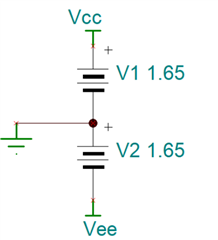
    3. Our Vcc is 3.3V and Vee is GND. From your simulations it looks different (Vcc = +1.65V and Vee = -1.65V) - is it makes any difference:

    4. If we will change also our cable to a lower capacitance value but Riso resistor will still be with a high value (for example 325 ohm) how it will affect on the stability issue?

    Thank you very much.

    Alex

  • Hi Alex,

    1. Can you please check what Riso resistor we need to drive our 2.5nF capacitive load but with OPA4991 (the same footprint as TLV2374) and of course 0 ohm resistor (for a real unity gain in R20 - instead of 10K as we have now)?

    Did you take a look at the video showing how to run stability simulations? In case you can't see the link, let me send it again: How to run op amp stability in Spice Simulations. Let me know if you have any questions on how to run the sims. 

    2. Is it possible to place Riso resistor at the beginning of the cable and not on the board in order not to change a PCB layout design?

    That's a question to your manufacturing team to see if it's feasible. 

    3. Our Vcc is 3.3V and Vee is GND. From your simulations it looks different (Vcc = +1.65V and Vee = -1.65V) - is it makes any difference:

    That's done to simplify the AC simulations. Essentially I do this to make the common mode voltage set to 0V rather than having to ensure we are at 1.65V. It won't result in any difference in performance of the op amp. 

    4. If we will change also our cable to a lower capacitance value but Riso resistor will still be with a high value (for example 325 ohm) how it will affect on the stability issue?

    It will change the phase margin. By how much, well that depends on how much the capacitor changes. You can see how it affects the stability in simulations. 

    Let me know if that clarifies things! 

    Best Regards,

    Robert Clifton 

  • Hello

    I never worked with PSpice before.

    I downloaded PSpice for TI

    But don't see the MMI as described in the link you attached.

    It is just an Orcad capture interface - for example no analysis button and etc..

    Also, how I can add a small signal source VG1 and Vo test point as shown in your simulation above?

    Thank you

    Alex 

  • Hi Alex,

    I was actually using Tina TI so the interface is going to look different. 

    Information on how to use this tool can be found on the Pspice for TI folder under the support and training section.

    If there's information you can't find, please let us know so we can help! 

    Best Regards,

    Robert Clifton 

  • Hell

    In this case I will download a Tina TI in a few days (as last time I downloaded PSpice my Orcad capture was damaged - and I must use Orcad now as I am in a final stage of new schematics design - not related to our discussed issue here).

    I have additional questions:

    1. On the input of the destination - LM7321 we have 3.32K resistor.

    This resistor was added just not to leave LM7321 input open in case of the disconnected cable.

    Now as I must add Riso resistor with a significant value on the other side of the cable - what you suggest doing with 3.32K resistor? To change a value to much higher one - like 1Mohm, or simply to remove this resistor (and leave LM7321 input open when cable disconnected) or something else?

    2. Regarding the damage of this LM7321 (that is powered by 24VDC) - absolute maximum rating of this op-amp is ~35V. Do you think that instability issue discussed cause to the oscillations above this value when the unstable source op-amp is powered only from 3.3VDC?

    Thank you.

    Alex 

  • Hi Alex,

    I didn't realize that installing Pspice could cause problems with your Orcad capture. Thank you for letting us know about this. 

    I have my answers to your questions/follow up question below:

    1. As you know there will be a voltage drop across the Riso. In this application, it's about 10% of the signal being dropped. I'm not sure if that is too much of a loss for your system. Usually we would recommend designing the system with an Riso + Dual feedback to compensate the voltage drop. Alternatively, if you can boost the input signal to account for this drop that would help too. 

    The reason for having this 3.32kohm resistor is to help minimize the effects of the input bias current seen on both inputs of the op amp. The parallel resistance of R7 and R6 give about 3.2kohm, (or 3.1kohm if R7 = 3.65kohm). The 3.32kohm tries to match the input impedance seen on the inverting pin.

    The reason why it's important to try to match the impedances is that the LM7321 has a large input bias current that isn't negligible compared to other op amps. To "cancel" the input bias current affects, you match both inputs.

    2. How did you confirm whether it was the output pin of U2 or the non-inverting input pin of U3? 

    Best Regards,

    Robert Clifton 

  • Hello

    1. We want to get 3V on the input of the U2 (this value set maximum illumination value).

    We also don't want automatically to increase the output value of TLV2374 to - for example 3.3V as it involves a software change that control the D/A.

    So, I understand that you suggest not to touch a 3.32K value of R5?

    2. You think that the instability issue of TLV2374 actually can damage U3.

    I checked the output of U2 (that is also connected to non-inverting pin of U3) and verified that the value was nearly 0V.

    I thought that the damage is only in the first stage - U2?

    Thank you.

    Alex

  • Hi Alex,

    1. Well if you want to minimize the voltage drop based on the change limitations you have, you will need to change R5. If you change R5, you need to change the resistors on R6 and R7 to match R5 (R5 = R6||R7).

    2. I want o confirm if the failure was on the input of U3 or the output of U2 since they are both directly tied to each other. Let's say if the ESD diode on the non-inverting input of U3 failed, shorting the input to ground. Since it's directly connected to the output of U2, it could also look like U2's output failed. That's why I'm wanting to know how you confirmed it was the output of U2. 

    Best Regards,

    Robert Clifton

  • Hello

    Regarding possible damage of U3 - in order to confirm it I can try to remove it and to see if there is an output of U2 without U3.

    You think that an input oscillation from TLV2374 and long cable can be amplified by U2 above maximum input rating of LM7321 (~35VDC) - even the power supply of U2 (and U3) is 24VDC?

    Thank you.

    Alex 

  • Hi Alex,

    Knowing what was damaged would shed insight on what was possibly going wrong. 

    It doesn't seem likely that the damage was occurring from the oscillations coming from the TLV2374. Not unless the 24V supplies hadn't turned on before the 3V supplies and there was an input signal going to the LM7321. But even then, I would expect to see the input pin of U2 to be damaged rather than somewhere between the output of U2 and the input of U3. 

    Best Regards,

    Robert Clifton 

  • Hello Robert

    Now started to work with TINA.

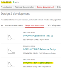
    1. Regarding OPA4991 was unable to find a normal simulation model - just TSM (of OPA2991) file from TI website.

    Is it possible to convert it to a normal simulation model for TINA?

    2. I found another quad component OPA4353 (that is quite expensive). But the results are too much good.

    With this component I need a very low value Riso that will lead to a very low signal drop.

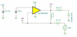
    Can you please approve my simulation. Do you have any comments?

    Thank you.

    Alex

  • Hey Alex, 

    You can just use the OPA2991 model found on the product page, the model is available for all channel variants: single (OPA991) and quad (OPA4991). 

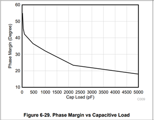
    Thanks for clarifying the cable length capacitance (either 600p or 2500pF), either way I think the OPA4991 can drive it although with varying phase margin (as you have seen in the training series Robert had linked) we recommend greater than 45 degrees of phase margin for robustly stable device. 

    The OPA4991 might be able to drive it without any BOM change (and marginal stability of 20 degrees). I think it's worth it to sample some OPA4991s and populated them in the place of TLV2374 (we have P2P compatibility):

    If the need for an RISO persists, please leverage the training series. 

    Please let us know if the issue is resolved. 

    All the best,
    Carolina 

  • Hello

    Thank you for your answer - maybe we will use OPA4991.

    I saw also OPA4353 - with this IC and very small value Riso (10 ohm - so there will be very small signal drop) we can get a very good phase shift.

    This component is quite expensive and looks very old - but what you say about it?

    Thank you very much.

    Alex

  • Hi Alex,

    I'll need to check the model to see if it's got the necessary components to properly model stability, but you can take a look at it on your board to see if it will work as well. 

    Best Regards,

    Robert Clifton 

  • Hello

    1. You wrote that you need to check the OPA4353 model. Is it means that maybe (a lot of) simulations done (by me with different op-amps and components) could be not correct - as the model could be non-updated one and etc?

    2. Observing the signals in the board show nothing extreme (like very high overshoots or a lot of ringing).

    Shown above a power up sequence. The strange form at the beginning is probably a power up initialization of the MCU and D/A (the board not designed by me - so it is just my guess).

    You think that we had to see something extreme by scope? The fact that it is not so indicate something?

    3. Actually, our real system connection could worse than the described (that we connect a single cable of up to 4 meters). In some of the systems we have 2 cables connected in parallel - one of them 4 meters and the second 1.5 meters while one of them (either 4m or 1.5m) is an open ended (where the specific wire of the TLV2374 op-amp's output is not connected anywhere and acts as a long antenna). Of course, we will fix this and will not allow to connect an open-ended wire in parallel.

    Thank you very much.

    Alex

  • Hi Alex,

    Two things. First, the model is an older one and from what I saw, it doesn't look like the output impedance matches well with what the datasheet shows. 

    Second, one of my coworkers also took a look at your circuit and thinks that not having any external resistor between VADJ IN and the non inverting input of U2 can be causing ESD/EOS damage. Is there a way to add resistance between PAD3 and pin 3 of U2? 

    Best Regards,

    Robert Clifton 

  • Robert 

    The leds board is very small and dense.

    But if it is recommended, I will try to add a series resistor between PAD3 and the cable with wire in the following way:

    Current 4m or 1.5m cable in addition to the high capacitance is also non-shielded - therefore maybe potentially also pick up a noise.

    1. What should be the value of the suggested Riso based on current parameters of the LM7321 and the cable (2.5nF for 4 meters or 1nF for 1.5 meters)?

    2. As the input signal will be significantly dropped, I must also change R5, R6 and R7 values to MegaOhms?

    3. You think that replacing a cable to better quality one (and shielding) can eliminate (or significantly reduce) a need of the new Riso?

    Thank you very much.

    Alex

  • Alex,

    1. What should be the value of the suggested Riso based on current parameters of the LM7321 and the cable (2.5nF for 4 meters or 1nF for 1.5 meters)?

    2. As the input signal will be significantly dropped, I must also change R5, R6 and R7 values to MegaOhms?

    I think it should be 3.32kohm resistor. My thought is to remove R5 so that you don't have the voltage drop across the resistor. As long as the grounds of the two boards are connected then this should be fine. If they aren't then get a much smaller resistor for R5. 

    3. You think that replacing a cable to better quality one (and shielding) can eliminate (or significantly reduce) a need of the new Riso?

    It's possible, but I think having resistance between the cable and the input of U2 is good no matter what type of cable you choose. 

    Best Regards,

    Robert Clifton

  • Robert

    1. What you say about replacing R5 instead of resistor by TVS?

    2. With TVS maybe I can eliminate a need of the new Riso (near U2) at all?

    3. Do you think I need to increase the R6 and R7 resistors connected to the inverting input of U2 to MegaOhms (while TVS as assembled instead of R5 resistor) - in this case what will be the effects of the input bias current between inverting and non-inverting inputs of the U2? Can I rely on the "infinite" impedance value of the non-inverting input of U2?

    Thank you very much.

    Alex

  • Hi Alex,

    1. What you say about replacing R5 instead of resistor by TVS?

    2. With TVS maybe I can eliminate a need of the new Riso (near U2) at all?

    A TVS diode will only protect the circuit from excess current if the voltage is above the breakdown voltage. I would still recommend including the series resistor to the input of U2. That said, including a TVS diode could help minimize potential damage. 

    3. Do you think I need to increase the R6 and R7 resistors connected to the inverting input of U2 to MegaOhms (while TVS as assembled instead of R5 resistor) - in this case what will be the effects of the input bias current between inverting and non-inverting inputs of the U2? Can I rely on the "infinite" impedance value of the non-inverting input of U2?

    I don't think you need to. The larger the resistor values are, the more the input bias current will increase the output offset voltage error in your circuit. 

    I wouldn't rely on the "infinite" input impedance of the circuit to try to "balance" your external resistances. 

    Best Regards,

    Robert Clifton 

  • Hello Robert

    1. So, if you suggest still to add a series 3.32K resistor - your recommendation is also just to remove R5 (both GND's of both boards are connected) and to work as below:

    Or the best will be to assembly also TVS instead of R5 (with breakdown of let's say around ~10VDC that is far away from the maximum amplitude from D/A of 3VDC and absolute maximum rating of LM7321 input pin ~ 35VDC) in addition to 3.32K series resistor as below?

    2. Still not clear for me regarding R5: You wrote before:

    "The reason for having this 3.32kohm resistor is to help minimize the effects of the input bias current seen on both inputs of the op amp. The parallel resistance of R7 and R6 give about 3.2kohm, (or 3.1kohm if R7 = 3.65kohm). The 3.32kohm tries to match the input impedance seen on the inverting pin."

    How impedance between (+) and (-) pins of the LM7321 will be matched if R5 will be removed?

    Thank you very much.

    Alex

  • Hi Alex,

    1. So, if you suggest still to add a series 3.32K resistor - your recommendation is also just to remove R5 (both GND's of both boards are connected) and to work as below:

    Or the best will be to assembly also TVS instead of R5 (with breakdown of let's say around ~10VDC that is far away from the maximum amplitude from D/A of 3VDC and absolute maximum rating of LM7321 input pin ~ 35VDC) in addition to 3.32K series resistor as below?

    Both options will work. There's added safety with the TVS diode being included compared to when it's not.

    If you do go with a TVS diode, then one that's set to 10V should work for this application. 

    2. Still not clear for me regarding R5: You wrote before:

    "The reason for having this 3.32kohm resistor is to help minimize the effects of the input bias current seen on both inputs of the op amp. The parallel resistance of R7 and R6 give about 3.2kohm, (or 3.1kohm if R7 = 3.65kohm). The 3.32kohm tries to match the input impedance seen on the inverting pin."

    How impedance between (+) and (-) pins of the LM7321 will be matched if R5 will be removed?

    The input bias current will still be affected by the new resistance that is being placed in series with the cable. Remember that current will flow whether to a resistor to ground or a resistor in series with the cable. That's why I recommended the same valued resistor that you had placed in R5 to now be in the Riso place. 

    Hope this clarifies things.

    Best Regards,

    Robert Clifton 

  • Hello 

    Regarding the driver side TLV2374.

    As adding Riso at the output of the op-amp stabilize the op-amp but cause to the signal drop in the receiver side (of course this is in case we don't want currently to touch receiver side like removing parallel connection of R5) I want to compensate this signal's drop by adding gain to the output op-amp.

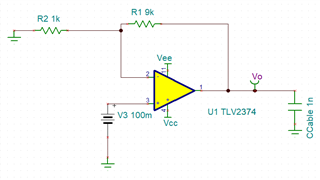
    Below some simulations made by me (to compensate signal drop of 4.33% in case of Riso=150 ohm):

    Above phase margin with gain: ~20deg (while in unity gain configuration of the op-amp it was >45deg).

    Below shown the results (phase margin of 43deg) when I decided to reduce values of the feedback resistors:

    Just wanted to verify that the results (that changed so dramatically -improvement of >20deg) are normal, and I can rely on the simulations?

    Thank you.

    Alex

  • Hi Alex,

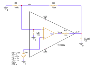
    Actually changing the feedback resistors to a lower value can improve stability. People often forget that the the input capacitance of the op amp interacting with the feedback resistor creates an RC filter, aka another source of delays. Here's an image to better explain what I'm talking about. 

    The input capacitance can't be changed. However the feedback resistor's value can be. Lowering the feedback resistor pushes the cutoff frequency to higher frequencies. The higher the frequency, the less likely the additional pole in the feedback loop will cause the op amp to be unstable. 

    Best Regards,

    Robert Clifton