This thread has been locked.

If you have a related question, please click the "Ask a related question" button in the top right corner. The newly created question will be automatically linked to this question.

JFE150EVM: PSRR of EVM Circuit

Part Number: JFE150EVM
Other Parts Discussed in Thread: OPA202, , JFE150

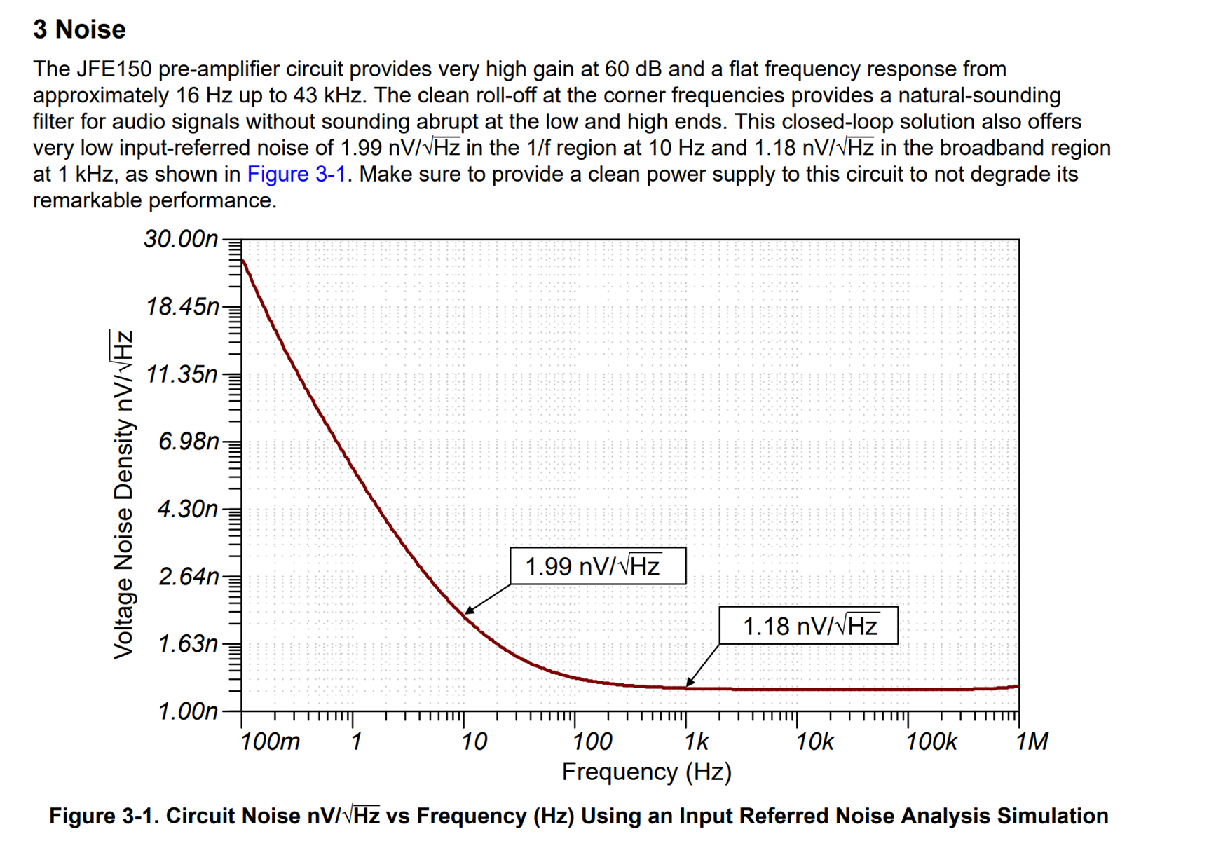
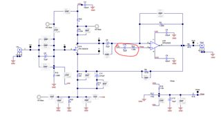
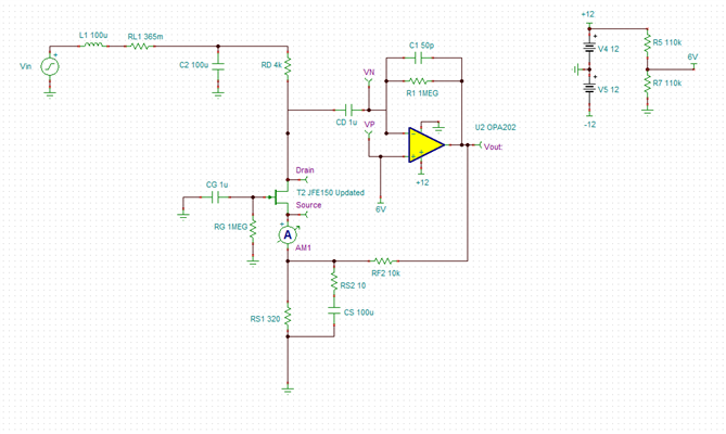
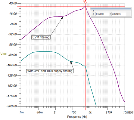
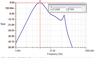
Hi, I note in the JFE150EVM there's an LC on the supply input, with a corner around 1 kHz or so. I'm wondering with 60 dB of gain how sensitive the Figure 4-1 circuit in the JFE150 Evaluation Module User's Guide might to supply noise? While the OPA202 has solid PSRR, the JFET configuration probably does not. In SPICE it looks like a 1 kHz tone injected on the 12V rail is mirrored almost 1:1 at the output, suggesting the supply might be a challenge. I'm looking at using a TPS7A series LDO with ~20 uV noise from 10 to 100 kHz for the +12V.

Thanks for any guidance

  • Hello, 

    Yes this configuration is highly dependent on a clean power supply. When I measured the noise of my evm with heavy power supply filtering I achieved results extremely close to the simulation shown below. In my application note for this circuit (link below) I highlight that a clean power supply should be used in order to not degrade the performance. 

    https://www.ti.com/lit/an/slpa018/slpa018.pdf?ts=1687191831014&ref_url=https%253A%252F%252Fwww.ti.com%252Fproduct%252FJFE150

    Best Regards, 

    Chris Featherstone

  • Hi Chris, thanks for the answer. The app note is excellent, BTW. 

    If you start with the JFE150 Piezo amp tina spice design (SLPM352), get rid of the input generator (short to ground) and replace the battery with a voltage generator with 12V of DC, and then sweep the AC response you see see considerably gain around 1 kHz. Which suggests the supply noise is amplified, so a negative PSRR 

    What I'm asking here is whether or not the "clean supply" has been quantified. Seems that if your supply doesn't have significantly better noise density than 1nV/rthz then you won't get the desired performance from this. And a power supply with that noise level is a long way from off the shelf 

    Or, the spice is leading me astray. Thanks!

  • Hello, 

    Thank you for the positive feedback on the app note! There was a lot to learn on our end when we first ventured into discrete JFETs. The PSRR of this circuit we knew would be a challenge early on. We never quantified a clean power supply. In order to measure the noise performance that matched very closely with TINA Ti, I used a 3 mF cap with a 100k ohm resistor on the supply. This adds a lot of power up RC settling time of course. I put some filtering on the supply line for the EVM but it was a trade off for the manufacturing of the boards. I couldn't make the test time too long. There is an experimental section on the EVM you may have noticed where I feed the power supply noise into the non-inverting terminal via another RC as shown below.  

    The idea is that the noise is fed common mode to the OPA202 such that I rely on the CMRR of the OPA202 for rejection. This was present during my measurements of the noise as well. The biggest challenge would be the 1/f noise with all the filtering. The lower the corner the higher the values are required which was the biggest challenge. 

    I did a very similar study in Tina. It's been a while since I looked at the details but you can see I added 365m ohms of series resistance I found from the inductor datasheet I was using at the time. 

    Below are two schematics I used. Both are the same except the supply line filtering. 

    With 100k and 3mF cap. 

    The way I looked at it in Tina was to view the gain vs frequency to see how much the supply noise would be gained up or attenuated. Although the input signal gain is a gain of 60 dB, the gain of the power supply signal is a max of 33 dB only at 1.6k. This is without the additional supply filtering. Using the 3 mF and 100k ohm resistor I see only attenuation of the power supply signal. I believe viewing from this perspective can help determine how much impact the supply has and narrow down a device to use. This is definitely the biggest challenge with this circuit. 

    Hope this helps. Let me know if I can be of further help. 

    Best Regards, 

    Chris Featherstone

  • Very helpful vectors Chris, thanks!

  • Hello, 

    Anytime! I did just realize I made a mistake I know I didn't make during measurements. The 100k R turns the device off due to the voltage drop. Sorry it has been a while since I looked at the PSRR in particular. I double checked the signal gain from the power supply with just the 3mF cap and it is about 7.5 dB of gain at it's peak shown below. Still far better than without filtering. 


    Best Regards, 

    Chris Featherstone