This thread has been locked.

If you have a related question, please click the "Ask a related question" button in the top right corner. The newly created question will be automatically linked to this question.

INA236: Current Reading Accuracy and Resolution

Part Number: INA236
Other Parts Discussed in Thread: INA229, INA228

Hello,

We are using INA236AIDDFR as current monitor in our system. We expect this chip can realize two functions in our product. (a) A highly accurate load current monitor. (b) Output an ALERT signal when overcurrent event occurs. My question in this thread focuses on function (a).

Below is part of the schematics related to INA236 in our product.

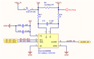
Here are some information about our circuit and design:

1. Bus voltage: 48V DC.

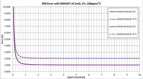
2. Tolerance of R8, R17 and R19 are all 1%. Tolerance of C35 is 10%.

3. ADCRANGE = 0, so shunt voltage input range is up to +/-81.92mV.

4. ADC conversion time: 140us for shunt voltage and 140us for bus voltage. We make this time short because in some overcurrent event we hope ALERT signal can be asserted as fast as possible.

5. Sample averaging number: 16. We set this number in order to avoid the impact from noise during current reading.

6. With the above conversion time and averaging number, the ENOB should be 15.1. So, we expect the resolution of current reading at 1.17mA.

We expect the current reading from INA236 can tell the difference of 1mA (or at least 3mA considering theoretical resolution of 1.17mA) when the load current is up to 10A. For example, we hope it can distinguish 8.005A from 8.008A in a reliable way. However, in the real test, we found the current reading was drifting. For example, when we expected a reading of 100mA, the real reading kept changing between 97mA and 103mA. The drifting range was around 5 to 8mA in our test. We tried both electronic load and resistive dummy load but got very similar result.

What I can think of as the reasons to make the reading drift probably are:

(a) the number of averaging, 16, was not enough to screen out the noise. Probably a higher number should be tried.

(b) 0.1% maximum gain error of the amplifier. But it seems this will not make the reading drifting several mA.

(c) some noise on the board created several uV voltage across the shunt resistor, which could result in mA current reading. Unfortunately, we don't have any equipment to measure the voltage in uV level.

(d) The real load current does drift. However, when we tested with resistive dummy load, we expect the load current should be quite stable.

Our questions are:

1. Is there any suggestion to make the INA236 current reading more stable?

2. More importantly, with our design (including components' tolerance), what can we expect as the resolution of current reading in reality? Do you know any application with INA236 can tell the difference in mA level?

Thank you!

  • Michael,

    Have you tried experimenting with different averaging values? I would generally agree with your analysis - most of the error sources on our devices should be relatively stable under steady operating conditions. If you increase the averaging value to filter out any noise you should be able to determine to what extent the noise is causing your error values. Another source of error you might want to consider is the temperature drift - Using our Excel Error Calculator I calculated that you might see as much as 1.5% error over the full temperature range - how much does the device's temperature change during operation?

    If the error you are seeing is due to noise, increasing the averaging samples is probably the most effective way to improve the resolution (remove the noise). I expect that you can reduce the noise down to the full resolution of the device if you are willing to increase the number of averages enough. The tradeoff that you have to accept for this solution is that the data will be available to the microcontroller at a slower rate as the device will be averaging more conversions.

    I also noticed that the common-mode voltage is at the limit of the device's range. Increasing the common mode voltage above 48V will cause the device to leave the linear range, and going above 50V may result in device failure, so you may want to ensure you are abiding by these device specifications.

    For reducing noise on the board, you may wish to increase the size of the shunt resistor, which will allow you to reduce the calibration register value. This will reduce the noise created between the shunt resistor and the INA236. For a maximum current of 10A you can use a shunt resistor of up to 8mΩ.

    You may also wish to increase the size of the capacitor or resistors on the input filter while staying within the datasheet guidelines. This will reduce current noise on the device inputs.

    2. More importantly, with our design (including components' tolerance), what can we expect as the resolution of current reading in reality? Do you know any application with INA236 can tell the difference in mA level?

    For your application it looks like the resolution is more dependent upon the surrounding circuitry, so It's hard for me to make a recommendation. The error due to the component tolerances can be calculated using the excel calculator I linked above:

    Let me know if my suggestions helped fix the problem,

    Levi DeVries

  • Hi Levi,

    Thanks for your reply and suggestions.

    We have noticed the temperature increase on the load resistor and even PCB board, but we didn't measure it. An estimation is around 40C when the room temp is 25C, we will try to do a measurement in the next test.

    We will also try to increase the averaging number to mitigate the impact from noise. Fortunately, data rate to the MCU is not a big issue in our application.

    The input voltage probably is a concern for us since you mentioned the device could leave its linear range. Is there any data that can show this impact from different input voltages?

    In fact, we want to use this current sensor as part of our overcurrent protection scheme (like an eFuse). Our current limit would be 10A. When there is transient overcurrent above 10A, we still hope the ALERT will not be asserted. While if the load is above 30A or 40A (such as a short circuit), we expect the ALERT signal will be asserted as fast as possible. That is the reason we use 2m Ohm shunt resistor so that the device can recognize 40A current.

    For the input filter, we would also try to fine-tune the value of resistors and capacitors to check if it can help.

    So, my understanding is, if all the configuration is correct, INA236 should be able to read mA level current reliably. Correct?

    Anyway, thanks for your suggestion and we will do more test in the following days.

  • Michael,

    We have noticed the temperature increase on the load resistor and even PCB board, but we didn't measure it. An estimation is around 40C when the room temp is 25C, we will try to do a measurement in the next test.

    This might account for some of the drift, but I suspect that noise on your system accounts for most of it based on your description. Since you said data rate is not a huge issue, increasing the number of averages would be a good way to reduce those errors. Keep in mind that with the max number of averages you will only get about 3.5 samples per second to the microcontroller (the alert will still operate at the same speed)

    The input voltage probably is a concern for us since you mentioned the device could leave its linear range. Is there any data that can show this impact from different input voltages?

    The device leaves the range that is specified by the electrical characteristics on the datasheet when it exceeds the recommended operating conditions, including the linear range of the device, so the behavior of the device is not specified if the common-mode voltage rises above 48V.

    If you are planning to operate close to this limit, you should also note that the Absolute Maximum Rating for the device is 50V, and beyond this limit the device may fail due to EOS. Any transient that might bring the common mode voltage above 50V should be treated as a potential failure event.

    The INA229 is another digital power monitor we offer that will tolerate common-mode voltages up to 85V if the INA236 doesn't have a large enough Vcm range for your application. The INA229 also has a larger sensing range, so you could use a larger sense resistor to reduce the effect of noise.

    So, my understanding is, if all the configuration is correct, INA236 should be able to read mA level current reliably. Correct?

    Anyway, thanks for your suggestion and we will do more test in the following days.

    The INA236 is capable of reading current at a mA level. The noise from the input circuitry is probably going to be your main hurdle in getting that level of precision, but the device is capable of the precision level listed in the ENOB.

    Most of our discussion thus far pertains only to the precision of the device (stability/repeatability or resolution) but you should also be aware that the accuracy of the device (how close the measured values are to the real values) will be limited by your design choices. The most significant effect in your system right now limiting the accuracy is the tolerance of the resistor, which at 10A and 1% will result in 100mA of error. This might not be a concern for your application if you are only interested in relative readings or calibrate these errors out of your system.

    Let me know if I can be of any more assistance,

    Levi DeVries

  • Hi Levi,

    Thanks for your reply and recommendation of INA229.

    We will do more test on INA236 and further investigation of INA229 (also INA228 with I2C interface). At this stage, I think I've got enough information to go ahead.

    Thank you!

    Michael