Because of the Thanksgiving holiday in the U.S., TI E2E™ design support forum responses may be delayed from November 25 through December 2. Thank you for your patience.

This thread has been locked.

If you have a related question, please click the "Ask a related question" button in the top right corner. The newly created question will be automatically linked to this question.

LM2904-Q1: lm2904-Q1 output

Part Number: LM2904-Q1
Other Parts Discussed in Thread: LM2904B-Q1

I have a question about LM2904AVQDRQ1 s application of Differential Amplification as the picture below.

The transport formular is Vout=3.3*(V+-V-)

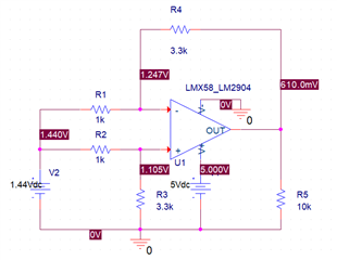
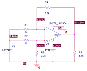
The Vout should be near 0V when V+ and V- are equal to 1.44V. But the simulation result and test result both are about 0.6V. The Vout voltage will decrease with R5 decreases.

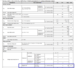
And the Vout_negative can be 20mV based on the datasheet.

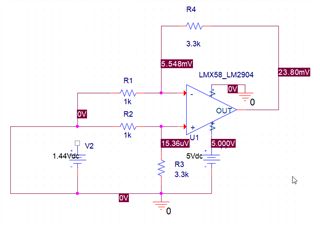
The Vout is near 0V when connect V+ and V- both to ground.

Could you please tell me the reason?


Looking forward to your reply!

Simulation1:V+ and V- both connect to 1.44V.

Simulation2:V+ and V- both connect to 1.44V with R5=10k
Simulation3:V+ and V- both connect to 1.44V with R5=5.1k
Simulation4:V+ and V- both connect to ground
Vout_negative voltage level in datasheet:
Kind Regards

Imelda

  • Hello Imelda,

    The VOL is under 20mV when load is 10k or less to ground of the op amp (pin 4).  The load is R4 and R5 ; this is a load terminated to voltage above ground.

    This is also in the data sheet. The sink current can be as low as 12uA with Vout at 200mV.

    The replacement LM2904B-Q1 minimum is a higher value of 60uA.

    For more information check out application note : section  3.1 ; Design Guidelines for Devices with LM324/LM358 Cores

    To get around this, the feedback resistors can be increased or Vref of the difference amplifier can be raised. 

  • As for application of differential amplification circuit, The common mode input will influence the output of the circuit according to the simulation. Is that formal phenomenon?

  • Hey Song,

    Check the current at the output of the amplifier, and through your feedback resistor. You will see as this value increases past a certain uA range (as Ron mentioned above), you will no longer be able to drive the output low enough to properly drive the inputs equal to each other. This is the effect of reaching the limit of the constant current sink.

    The solution to this is to either:

    1. Use an amplifier with a true rail to rail input/output
    2. increase the value of the feedback resistor so the op amp does not have to sink as much current to drive the output low
    3. Increase your Vref

    2 and 3 were already suggested by Ron above.

    Best,
    Jerry