This thread has been locked.

If you have a related question, please click the "Ask a related question" button in the top right corner. The newly created question will be automatically linked to this question.

LMH6629: Negative offset

Part Number: LMH6629


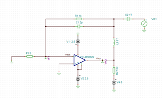
Hi I'm having issues with a large negative offset appearing at the output of the LMH6629. I have attached an image of the circuit schematic 

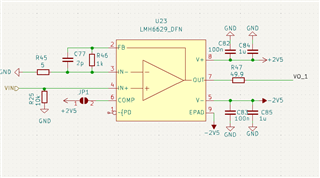
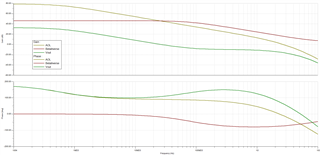
LMH6629 is setup in a +/- 2.5V bipolar configuration. in the 4 V/V mode. I am using the DFN package with the feedback pin. Please note that the source resistance is 260 ohms, and it isn't indicated on the schematic.The cutoff frequency is around 8MHz. For another reason I not understand, 2pF gives this cutoff instead of the 20pF one would expect from calculating 1/2piRC. Is this due to the internal compensation in 4 V/V mode? 

If I am correct, the offset should be calculated(in Latex for ease of viewing) via Vo = 1+ \frac{R_f}{R_g}(V_{in}+ V_{os} +(I_{b+}\cdot R_s)) -I_{b-}\cdot R_f . This formula is calculated assuming the bias current flows out of the inputs of the amp. Therefore, in my configuration we should expect the larger source resistance to be the dominating factor in determining the offset, which should therefore be positive. I am however instead seeing a negative offset as mentioned, and quite a large one at that(up to -6mV referred to input)

My suspicion was that the impedance seen be the inverting terminal was far too low, as section 7.3.3 of the datasheet indicates it should be above 25 ohms. However, no matter the configuration I use, I always see a negative offset. I have tried to drastically reduce the gain down to even Av =15, to increase Rg up to 100 ohm, and to match Rs to Rg in parallel with Rf to reduce the impact from the bias currents. I even tried using the SOT-23-5 package but no difference. 

Any thoughts or assistance would be greatly appreciated. Can clarify any points needed/add scope captures. 

  • Hi Nathan, 

    The offset is likely caused by the bias current in conjunction with the fairly high source impedance. A simple experiment would be to reduce the 10k resistor on the non-inverting input to something like 50 Ohms and see if the offset changes. 

    The inverting input bias current is only gained by the parallel combination of Rf and RG so very small in your case because of the 5 Ohm resistor. That will let the non-inverting bias current dominate and cause a large offset. 

    Regards, 

    Jacob 

  • Hi Jacob, thank you for your quick response!

    So, I've experimented with lowering that input resistor to 100 ohm and unfortunately the negative offset is still present.

    I had a bit of a discovery today however. Removing the feedback capacitor gets rid of this negative offset, and instead reverts it to a positive value and behaves as one would expect. Is it possible a leakage current through the feedback capacitor could be causing this effect? I'm a little stumped. 

  • Hi Nathan, 

    That makes sense, I should have caught that in my initial review. You don't want to have a feedback capacitor connected when using the amplifier in the 4 V/V gain setting as it will cause it to be unstable. In that setting the amplifier is not unity gain stable and a feedback capacitor causes the amplifier to have a high frequency gain of unity so it will cause stability issues. 

    Regards, 

    Jacob 

  • Hi Jacob,

    Thanks for the help! I'm guessing the same happens at 10 V/V setting as it is also not unity gain stable. 

    My apologies, I am not sure I completely understand the explanation. Would you mind elaborating the explanation? Am I right in thinking that with the feedback capacitor present we are forcing the amp's noise gain to unity gain at the higher frequencies, whereas without it it is only the AOL limitations that are reducing the gain? What happens at the frequency where AOL intersects unity? 

  • Hi Nathan, 

    Yes you are absolutely correct. The capacitor forces the amplifier's noise gain to unity. Because this is a decompensated amplifier, that means that it has a second pole in the open-loop gain response. If the noise gain is unity, both of these poles will be present in the loop response and cause too much phase shift resulting in instability. 

    Regards, 

    Jacob 

  • Thanks for the help Jacob, appreciate it. Resolving this thread now!

  • Jacob, I'm sorry to bother you again. I'm trying to make sense of a SPICE simulation I am doing of this circuit. I'm trying to see this instability from the ROC when 1/Beta intersects with the loaded open loop gain. However the ROC at this intersection suggests stability as it 20dB a decade. 

    Why would this be the case? I'm guessing I've simulating something incorrectly/just mis-understanding so I'm also including my SPICE schematic below. AOL is Vout/Vf1 and 1/Beta is 1/Vf1.  

  • Hi Nathan, 

    This is interesting, your simulation is correct. I had made the assumption that the zero in the 1/Beta caused by the feedback capacitor would occur within the bandwidth of the amplifier. However, the simulation is showing that the circuit should actually be stable as the loop gain reaches zero before the phase shift caused by the feedback capacitor can have an affect. 

    It's certainly possible that there are other parasitic element from the board/components/etc. that may be causing additional capacitance and making the circuit unstable. You could try adding an few extra pF in the simulation and see how that changes the output. Certainly if you make CF large enough it will cause the circuit to oscillate. 

    Best, 

    Jacob