This thread has been locked.

If you have a related question, please click the "Ask a related question" button in the top right corner. The newly created question will be automatically linked to this question.

LMC6001: LMC6001

Part Number: LMC6001
Other Parts Discussed in Thread: INA149

Dear TI:  I would like to build a basic electrometer amplifier with your LMC6001 amplifier.  Can you please provide me with a design schematic and materials list for an electrometer amplifier that will be used to measure voltage on pF capacitors?  Thank you, Allen Hebert.

  • Hi Allen,

    According to the Keithley Low Level Measurements Handbook: An electrometer is a highly refined DC multimeter. As such, it can be used for many measurements performed by a conventional DC multimeter. Additionally, an electrometer’s special input characteristics and high sensitivity allow it to make voltage, current, resistance, and charge measurements far beyond the capabilities of a conventional DMM.

    I can certainly advise you on using the LMC6001 to make these types of measurements. I see you are specifically interested in measuring voltage across pF capacitors. May I ask how this voltage is being generated? Are these capacitors connected to a larger circuit or sensor? What is the magnitude of voltage you are trying to measure? Is this a DC or AC voltage? If AC, what is the frequency?

    If you can tell me more about the application and any specific design requirements, I can help you come up with an amplifier schematic that meets your needs. Just to let you know, besides specific TI amplifiers or other TI devices I will not be able to provide a complete materials list for your final design. I can advise the general component values and materials needed for your amplifier circuit (ie. resistors, capacitors, etc)

    Regards,

    Zach

  • Hi Zach:

     Thank you for offering to help me!

    I have built two parallel plate capacitors (capacitor A & capacitor B).  They are each in the 5nF range.  The capacitors are designed so that I can separate the + and − plates and switch them between the capacitors.  For example, I can assemble the A+ and B− and B+ and A− plates and then take new voltage measurements on both capacitors.  I can also arrange the A+ and B+ plates and A− and B− plates and again take new voltages on both capacitors.

    In theory, the voltage measurements between the switched A+/B– and B+/A− plates should essentially be the same as the A+/A− and B+/B− plates.  Likewise, in theory, the voltage measurements between the A+/B+ and A−/B− should be 0VDC.  However, in practice, it is unlikely that the above measurements will be the same as the theoretical measurements.  Therefore, I would like to use an electrometer amplifier and take precise voltage measurements.  The measurements are important to me for a separate capacitor project.

    I can buy off-the-shelf electrometer amplifiers from Leybold, Pasco, and 3B Scientific (links below).  However, I would much rather build it myself.  I have not yet found any basic electrometer amplifier circuit schematics online that I can use to build my electrometer amplifier.  I have included the links for the closest examples that I could find (see below).

    Here are my answers to your questions:

    1.  Are you specifically interested in measuring voltage across pF capacitors?  The capacitors that I built are in the 5nF range.  I am interested in measuring the voltage across the capacitors as described above.

    2.  May I ask how this voltage is being generated?  The voltage will be generated by a series of 9VDC transistor batteries with a potentiometer to allow 0VDC to 100VDC output.

    3.  Are these capacitors connected to a larger circuit or sensor?  These capacitors are not connected to a larger circuit.

    4.  What is the magnitude of voltage you are trying to measure?  The maximum voltage that I will measure is 100VDC.

    5.  Is this a DC or AC voltage? If AC, what is the frequency?  I will be working with DC voltage.

    I hope that above is helpful.  I look forward to hearing from you!

    Thanks,

    Allen

    Off-The-Shelf Electrometer Amplifiers

    1. https://www.leybold-shop.com/physics/physics-equipment/electricity-electronics/electrical-measuring-instruments/measuring-amplifiers/electrometer-amplifier-53214.html
    2. https://www.pasco.com/products/lab-apparatus/electricity-and-magnetism/electrostatics-and-electric-fields/es-9078
    3. https://www.3bscientific.com/us/electrometer-230-v-5060-hz-1001025-u8531408-230-3b-scientific,p_612_16606.html

     Example Electrometer Amplifier Circuits

    1. http://graphite.chemistry.nd.edu/hardware/post/electrometer-build-instructions/
    2. https://scholarworks.wmich.edu/cgi/viewcontent.cgi?article=4276&context=honors_theses
    3. http://amasci.com/electrom/sas51p1.html#Electro
  • Hi Allen,

    Thanks for the detailed description. It may help my understanding if you are able to provide a schematic of your voltage generator and how it is connected to the capacitors. 

    In theory, the voltage measurements between the switched A+/B– and B+/A− plates should essentially be the same as the A+/A− and B+/B− plates.

    I agree with this, the voltage will be set by your voltage generator. Therefore I believe this measurement is simply the output voltage of your generator? Can you clarify?

    in theory, the voltage measurements between the A+/B+ and A−/B− should be 0VDC

    See above, if both plates are connected to the same node, you will measure the same potential voltage.

    The voltage will be generated by a series of 9VDC transistor batteries with a potentiometer to allow 0VDC to 100VDC output.

    I would caution operating above 50V, as anything above 50V is considered "high-voltage" in the electrical industry. Additional safety precautions must be taken to ensure when >50V is present in a live circuit. This is especially dangerous when it comes to exposed capacitive plates that you are planning on handling and switching around. Capacitors will hold their charge for a very long time unless a low impedance path is available to safely discharge.

    A common failure mode occurs when the circuit is powered off, but the capacitors continue holding the 100V potential because they were not given a path to discharge. Somebody assuming the circuit is powered off and safe touches the assembly and the capacitor is discharged into their body.

    Typically only individuals with a special high voltage training can work with >50V and the entire circuit and connections must be enclosed in a high-voltage box.

    Furthermore, the LMC6001 is a 15V device with an absolute maximum of 16V. Anything above the abs max will damage the device.

    It sounds like you are trying to measure a small differential voltage in the presence of a high common-mode voltage. If this is the case, a difference amplifier such as INA149 will be better suited for your design.

    https://www.ti.com/product/INA149

    Regards,

    Zach

  • Hi Zach:

    My voltage generator is just several 9VDC transistor batteries connected in series.  Like you suggested, I will limit my working voltage to < 50VDC.  That is, I will charge my home-made capacitors to < 50VDC.  Then, I will use a voltage divider to reduce the voltage input to the LMC6001 circuit to 15VDC.

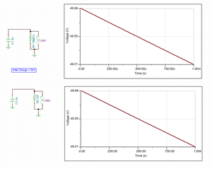
    It might be better for me to explain my project as follows:  If I charged a 1nF capacitor to 50VDC and then measured the voltage using a standard DMM with 10MΩ input impedance, the capacitor would discharge to 49VDC in just 2x10⁻⁴ seconds.  However, if I charged a 1nF capacitor to 50VDC and then measured the voltage using an electrometer amplifier with 10TΩ input impedance, the capacitor would discharge to 49VDC in 202 seconds.  Therefore, I could essentially measure the voltage without discharging the capacitor.  I would like to connect my voltage generator to my home-made capacitor, charge my capacitor to 50VDC, disconnect my voltage generator, and then measure the voltage on my capacitor for about one minute essentially without discharging it.

    Based on the above, is the LMC6001 the correct IC?  If yes, does TI have any DIY Op Amp evaluation kits or schematics that I could use to build an electrometer amplifier?  I found some DIY Op Amp evaluation kits at https://www.ti.com/tool/DIYAMP-EVM?login-check=true#tech-docs.  They appear to be exactly what I am looking for except for an electrometer amplifier.  Can I use any of the eleven DIY circuits on the EVM boards to build an electrometer amplifier?

    Thanks,

    Allen

  • Hi Allen,

    Thanks for the clarification, I believe I understand your requirements. Your require a high-impedance amplifier so that when you disconnect the supply voltage from your capacitor, the cap voltage is maintained and measured for a long period of time.

    I see in your example you are using the RC time constant to determine the discharge time according to the equation: Vcap(t) = V*e^(-t/RC)

    With these assumptions, you are correct that a higher R will allow the cap to hold its voltage for longer.

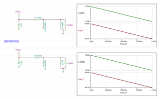
    Now if you plan to use a voltage divider to reduce the 50V to safe and measurable range for the LMC6001, you are actually reducing the effective input impedance of the amplifier. See below, the effective impedance is now limited by the impedance of the voltage divider, in this case 14.3 MΩ. It is not practical to use resistor values much higher than this, so the resistor divider cannot be used. You will need to lower your max capacitor voltage.

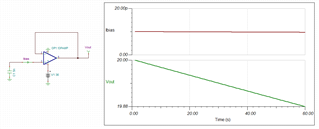
    See, the input impedance of an amplifier is actually determined by the input-bias current (Ib) of the input transistor pair. If you remove any resistor dividers from your circuit and connect the capacitor directly to the amplifier inputs as shown below, the capacitor will discharge according to the following equation:

    Ib = C*dV/dt

    Where, Ib is the input bias current of the amplifier and dV/dt is the change in voltage over time.

    See for a generic op amp, with an Ib of ~10pA, the voltage droops by 120mV over the 60s interval.

    You can determine you Ib requirements depending on the amount of voltage droop is tolerable over the 60s interval.

    For example, if you lower your input voltage to 20V and require 0.1% error over your 60s interval:

    5nF x (20mV / 60s) = 1.6667pA

    Keep in mind that for most amplifiers, the Ib will increase as the input voltage increases, which is another argument for greatly reducing your input voltage.

    Is there a reason your input voltage should be so high? Can you reduce to 10V? 20V? 30V?

    What is your required measurement resolution / error tolerance?

    Thanks,

    Zach