Hi ti support team
1. What is the output efficiency of the positive and negative terminals of the power supply compared to the output terminals?
2. If the output is 20mA, what is the current on the power side?
This thread has been locked.
If you have a related question, please click the "Ask a related question" button in the top right corner. The newly created question will be automatically linked to this question.
Hi ti support team
1. What is the output efficiency of the positive and negative terminals of the power supply compared to the output terminals?
2. If the output is 20mA, what is the current on the power side?
Hi Rain,
1. What is the output efficiency of the positive and negative terminals of the power supply compared to the output terminals?
You have to look at the issues from the laws of thermodynamics, where Power_in = Power_out.
Power_in in this case = Vcc * Icc + Vee*Iee (Vcc is positive supply rail, and Vee is the negative supply rail).
Power_out = Vout*Iout
Sum_of_Power_in = sum_of_Power_out + sum_of_Power_loss
The Power_loss in power amplifier are mainly: Quiescent current power loss, Iq , where (Vcc - Vee)*Iq are the sum of DC power losses.
In terms of AC power losses: (Vcc-Vout)*Icc, where the Icc is the positive current going through the driving elements on the Vcc supply rail, BJT, Mosfet or other control elements.
(Vee - Vout)*Iee, where Iee is the negative current going through the driving elements on the Vee supply rail.
The %output_efficiency = 100* sum_of_Power_out/sum_of_Power_in
This is similar to %power_efficiency calculation in linear regulator (LDO) or switching power supply. In an example of switching power supply, 93% power efficiency means that 93% of input power is converted to the output power, 7% is the power loss in the switching elements and drivers. In LDO, this efficiency is much lower. The power amplifier is no different, and the efficiency is not high, because this is linear operations, which are Class A, B or Class AB power conversion operation. If higher power efficiency is required in op amps, Class C or D may be needed, but these amplifiers will introduce the distortion and higher harmonics etc.. It is used for different applications.
2. If the output is 20mA, what is the current on the power side?
In OPA454 op amp, the output current and input current is sort of independent as Clemens pointed out.
Here is a DC regulator example.. If I have 100Vdc, 10mAdc (1W of input power) linear regulator at input, the output can source up to 10Vdc, 100mAdc if it is 100% efficient.
If the regulator is 20% efficiency, then the output of the regular can only source up to 10Vdc @ 20mAdc.
The power amplifier works in the similar manner.
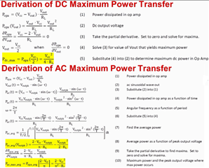
If you are interested in the subject, please send me the OPA454 or similar schematic, and I will be happy to simulate the cause and effect of %power_efficiency in Tina. Here is a power equation slide that are used if you'd like to calculate DC or AC power transfer in amplifier.

I am going to close this inquiry for now. If you have other questions, please let us know.
Best,
Raymond