This thread has been locked.

If you have a related question, please click the "Ask a related question" button in the top right corner. The newly created question will be automatically linked to this question.

XTR117: Long distance transmission for analog signal

Part Number: XTR117
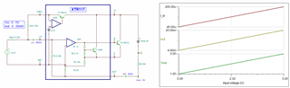
Other Parts Discussed in Thread: XTR115, XTR116

Hi,

Application: Analog 0V-5V to 4mA-20mA

I am looking for current loop IC (2 wire) which can transmit signal across 5m or more cable distance .

1. Can you provide suitable IC options?

2. What measures we need to implement if we are using same power source(Vloop) which is providing power to different electrical circuitry in the system?

Thank you

  • 1. You can use any 2-wire transmitter. The XTR117 is the simplest one, if you do not need additional features.

    2. The power source must be able to supply enough voltage and current for all devices.

  • Hi,

    From datasheet graph of XTR117 seems to supply 4mA of current.
    If we extend the graph, is the IC capable to drive 6mA typical & 10mA maximum current without falling below 4.5V?

    If not, can be bypass the Vreg pin without any circuit connection? or any circuit is needed for IC to work?
    There is reference circuit for bypassing Vref pin, do we have similar circuit for reference?

  • The loop current powers both the XTR117 and your circuit connected to VREG. The XTR117 takes at most 250 µA, so if you want to be able to output 4 mA, your circuit must not take more than 3.75 mA.

    If your circuit is powered by another supply, then leave VREG open.

  • Hi Prathmesh,

    1. Can you provide suitable IC options?

    Thanks for Clemens comments! XTR115/XTR116 and XTR117 are all good options for the 4-20mA, 2-wire current loop transmitter. Among these ICs, there have different board features (regulator voltages); you may select one that is the best suited for your application. 

    Enclosed is the XTR116 /XTR117 reference design. 

    https://www.ti.com/lit/ug/tiduao7/tiduao7.pdf?ts=1687469451091&ref_url=https%253A%252F%252Fwww.google.com%252F

    We also have numerous applications and training videos on the topics. Please visit these links if you want to the topics in details. 

    https://e2e.ti.com/support/amplifiers-group/amplifiers/f/amplifiers-forum/945188/faq-designing-with-4-20ma-current-loop-transmitters-xtrs-faq-links

    2. What measures we need to implement if we are using same power source(Vloop) which is providing power to different electrical circuitry in the system?

    Below are the key take away from the 2-wire transmitter design: 

    1. As Clemens pointed out, the sum of all input to output current flow without input signal has to be less than 3.75mA (lower would be better). 

    2. There is only ONE GND allowed in the entire 4-20mA system, typically the GND is allocated at Vloop side (this is low cost approach). Otherwise, you may have to use isolated Vloop supply, if you reference the GND elsewhere in the loop, for instance, in the analog input front end. 

    3. If GND is allocated at Vloop terminal, then XTR117's input signal references are referenced to Iret or pin3 node of the XTR117. In other words, all the input signal and Vreg are "floating" and they are measured with respect to Iret or pin3 terminal (important to remember). Vreg is measured w.r.t to Iret or pin3, which it should be measured at 5V. If Vreg or pin8 is measured with respect to GND, it will have different voltage, which it may seems "incorrect", because Vreg voltage is measured against a wrong reference --> it has to be w.r.t. Iret or pin3. 

    If the application has to input voltage signals from sensor, op amp or other measurement devices, the input signals have to be referenced to Iret or pin3 as well. Any other external regulator used in the design, it has to be measured w.r.t. Iret or pin3 node. The external regulator has to be referenced to GND and sourced at Vloop. And it has to comply to rule in 1 above. 

    XTR117 06222023.TSC

    The current gain within the XTR11X is 100 A/A. It is calculated as R1/R2 + 1  = 2.475kΩ/25Ω = 100. 

    4. You mentioned that length of wire is 5m or greater --> it needs to be twisted pair as shown in the drawing above. 

    can transmit signal across 5m or more cable distance

    5. Ros and Rset resistors in the simulation need to be precision resistor, which is better than 0.1%, prefer 0.05% or 0.01% in tolerance (depending on your design requirements). 

    6. 250Ω at Iout is to convert the loop current into voltage or ADC. The resistor or 250Ω needs to be precision resistor as well, otherwise Iout * 250 will have conversion errors. 

    If we extend the graph, is the IC capable to drive 6mA typical & 10mA maximum current without falling below 4.5V?

    When there is no input signal, Iout has to be less than 3.75mA in the system --> this is the requirements, otherwise, you will not have 4mA-20mA output as a function of the input. 

    Please provide me with the design requirements, if you have a special V-to-I conversion. 

    Best,

    Raymond

  • Thank you!

    Requirement is like to transmit analog voltage 0-5V to 4mA to 20mA.

  • Hi Prathmesh,

    Requirement is like to transmit analog voltage 0-5V to 4mA to 20mA.

    In the replied above, the simulation is enclosed. 

    If you have additional questions, please let us know. 

    Best,

    Raymond

  • Hi Prathmesh,

    I am going to close this inquiry, since we have been exchanging email in the E2E private messaging. 

    Best,

    Raymond