This thread has been locked.

If you have a related question, please click the "Ask a related question" button in the top right corner. The newly created question will be automatically linked to this question.

TLV9002-Q1: Error analysis within common mode input voltage range

Part Number: TLV9002-Q1

Hi team, 

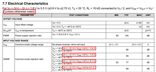
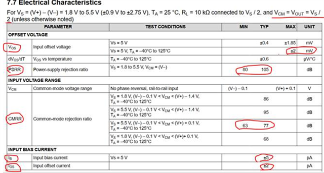
Below EC table spec is at VCM=Vs/2. Customer would like to evaluate the full VCM range (from V- -0.5 to V+ +0.5V)  output error, how to evaluate below factors variation with CM range?

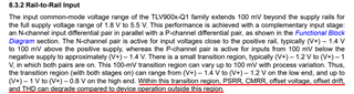
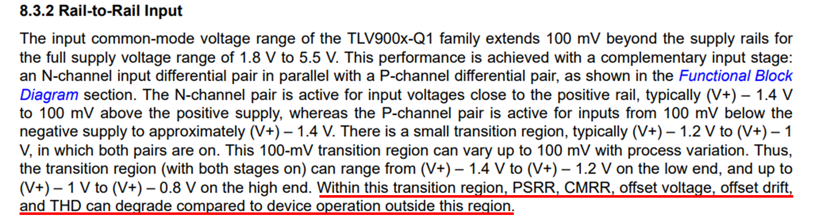
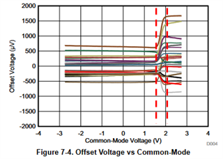
I see in the figure section we only has ios ibias and Vos with VCM figure, how to evaluate the PSRR and CMRR change with CM voltage? Thank you! 

Thank you

Scarlett

  • Hi Scarlett, 

    For CMRR, our electrical characteristics table does show typical CMRR across the range of Vcm as shown in the Test Conditions column. The condition of Vcm = Vs/2 is applicable to all specs unless otherwise noted and in the case of the CMRR spec, we list out the conditions of Vcm for each line item. 

    For PSRR, as explained in Section 8.3.2 of the datasheet, performance is expected to degrade in the transition region similarly to CMRR. We do not provide the typical curves across Vcm, but I can take some sample data to help give an understanding of the change across Vcm. Please note that this will be an isolated sample set of a few units and cannot be used as a statistical distribution or typical datasheet behavior. 

    Please let me know if you have any questions.
    Thank you!

    Best Regards,
    Ashley

  • This 5-1.4=3.6V, 5-0.8=4.2V, which means that the accuracy of the input common mode voltage between 3.6V and 4.2V (PSRR, CMRR, Vos, Ib, etc.) cannot be guaranteed, right?

  • Hello QWB,

    It is not the accuracy of the input common mode voltage that this paragraph is referencing. What is happening is that in this transition region, there are certain specifications like offset voltage, CMRR, PSRR, etc that could shift or change when compared to operation outside of the transition region. This can be seen best in Figure 7-4 in the datasheet as shown below. The transition region is outlined in the dashed red lines and show that a device can shift offset voltage in the positive or negative direction but this is not certain and can vary device-to-device.

    Please let me know if you have further questions.
    Thank you!

    Best Regards,
    Ashley

  • Thanks for replying,Can you give me the offset voltage, CMRR, PSRR,etc at V+=5V,V-=0V。Thanks

  • Hello QWB,

    The transition region will be a relatively constant voltage away from your positive supply rail, regardless of if your supplies are +/-2.5V, 5V/0V, or 15V/10V. Regardless of your supply voltage, your transition region will be roughly 1V below your positive rail. Your high CMRR region will be when you're input common mode range is between 0 and 4V.

    Specs like CMRR and PSRR are a function of your offset voltage, and can be found with the following equations.

    CMRR = (ΔVCM)/(ΔVos)

    PSRR = (ΔVsup)/(ΔVos)

    Since the transition region introduces larger offset, this will degrade CMRR/PSRR. The key information here is that if the input common mode (Vicm) remains within the range of V- ≤ Vicm ≤ (V+ - 1V), you will remain in the region with high CMRR, PSRR, THD, etc.

    More information on this can be found in the following TI Precision Labs Videos.

    CMRR: https://www.ti.com/video/4662542619001 

    PSRR: https://www.ti.com/video/4662585116001 

    Best,
    Jerry