This thread has been locked.

If you have a related question, please click the "Ask a related question" button in the top right corner. The newly created question will be automatically linked to this question.

LMC6484: "rail-to-rail output swing" at low output load has increased since SOP

Part Number: LMC6484

We use the operational amplifier LMC6484AIM in our products and have noticed that the value of the "rail-to-rail output swing" has changed from the time of series introduction until now.

At the beginning of production, the maximum ADC read values with open inputs (as shown below, 100k vs. GND) were set to a value that all PCBs in the first batch met (in the range of ~10mV).
In the past, these limits were allready raised once, because more and more boards did not meet the specs and recently again more and more boards are failing the test (and apparently without changes in the circuit).

I am aware that the chosen voltage value was very low, but at that time it was suitable for all boards and over time it seems like it has increased.
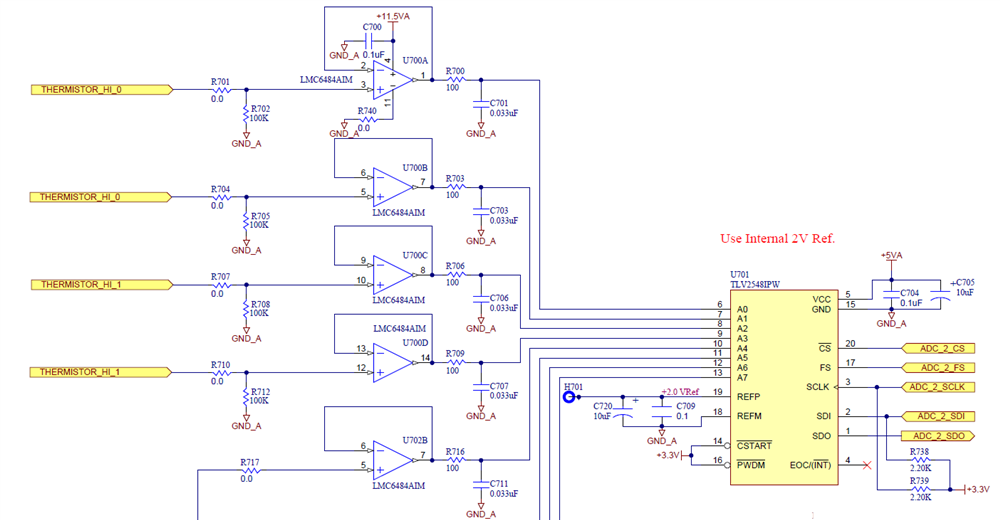
Fortunately, this does not seem to have a negative impact on the function of the device, so we can raise the limits to a higher value. However, it would be good to know if there are production-related reasons for this or if something else in our circuitry is the cause.

Could it be that this happened due to an intermediate change from LMC6484AIm (Non-RoHS & Green) to the type LMC6484AIM/NOPB (RoHS & Green) or is this a normal series variation of components and the differences simply come from using different component batches?


Thank you in advance for your support.

  • Marinus,

    This issue may be related to output swing, but could also be a number of other problems.  Please help me analyze your situation by doing the following tests.

    1. On a device that you think has this issue, please measure the output directly with a digital multimeter (with respect to GND).  Do this with the ADC converting and not converting.  Do you see a difference when the ADC is converting?
    2. Disconnect the amplifier output from the ADC by desoldering the 100 ohm resistor.  Measure the amplifier output before and after disconnecting the amp.  Do you see a difference?
    3. Look at the amplifier output with and oscilloscope.  Do this while the ADC is converting.  Does the signal look steady or is there a lot of noise on it?
    4. Possible issues:
      1. the ADC acts as a load.  The amount of current drawn by this load will increase at higher sampling rates.  The ability of an amplifier to swing close to a supply rail is dependent on the load current.  If the load current is higher the swing to the rail will not be as good.  If the issue is swing to the rail, decreasing the sampling rate can help. 
      2. The ADC also introduces a transient into the amplifier output.  The amplifier will have to settle to this transient.  Settling issues can look like a DC error, but really are because the amplifier bandwidth and filter are not optimal.  We may need to adjust sampling rate, or the RC value if this  is the issue.
      3. The ADC transient current demand can also exaggerate stability issues.  That means when the ADC conversion starts the amplifier may ring and oscillate.  I don't think that is the issue here, but we shouldn't rule it out completely.

    I look forwarded to hearing how your experiments go.  I hope we can resolve your issue soon.

    Best regards, Art

  • Art,

    Thank you for the quick and substantiated answer, these are all good points, which I will try to check in the next time.

    Thank you very much for your help so far.

    Best regards
    Marinus