Because of the Thanksgiving holiday in the U.S., TI E2E™ design support forum responses may be delayed from November 25 through December 2. Thank you for your patience.

This thread has been locked.

If you have a related question, please click the "Ask a related question" button in the top right corner. The newly created question will be automatically linked to this question.

PSPICE-FOR-TI: Overshoot at the Inverting Op Amp

Part Number: PSPICE-FOR-TI
Other Parts Discussed in Thread: OPA858

Hi all,

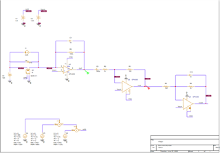
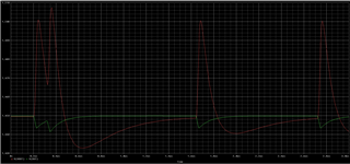
I have been designing an amplifier circuit for an APD signal. This circuit will have an ideal gain of 10M. However, since this APD is sensible to various noise sources, I will apply bandpass filters during the amplification stages. The 1st stage is composed of a transimpedance amplifier (TIA) to convert the APD current to a voltage (V_TIA = I_APD*100k). In this stage, I used a low pass filter with a cut-off frequency of around 1,5MHz. In the 2nd stage, I used an Op Amp with an inverting configuration with a gain of 10. I also added a high pass filter with a cut-off frequency of 530kHz (due to the 300pF capacitor). Here is where the problem happens. At the Op Amp output (red line) appears an overshoot due to this high pass filter. Do you know why I have this problem? How can I fix it? I would like to have this high-pass filter and also reduce the overshoot as much as I can.

I have below the images of the circuit and its simulation results. I also have a zip of the simulation.
OPA858.zip

Thank you in advance.

Best regards,

João Rego

  • Hello João,

      For the stage where you model the APD, does the gain block take in different voltage sources, or is the combination the expected signal response from the APD? 

    Thank you, 
    Sima 

  • Hello Sima,

    The APD model is just a combination of the expected signal response on the APD. Basically, the APD will receive the 2 pulse signals and then, after a while, just 1 pulse signal.

    Best regards,

    João Rego

  • Hello João,

    Looking at your results the issue, like you mentioned, might be the high pass filter. The lower frequencies of the signal are getting cutoff; therefore, a lower cutoff frequency might be you something to consider so increasing the 300pF capacitor. This should give the result that is expected at the output of the second stage.

    Another thing to consider is the input signal to the TIA stage. It looks like the input signal's rise time (1ps) is too fast which will result in some form of distortion at the output (green signal).

    Best Regards,

    Ignacio

  • Hello Ignacio,

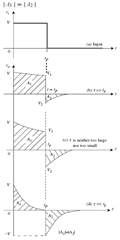
    From what I searched on the internet, the problem is really the high pass filter. The first consideration when designing a high-pass filter is the cut-off frequency. However, I have to consider the step response of an RC high-pass circuit, since the TIA output is almost a pulse.

    The RC high pass filter design of a step response is a trade-off between voltage overshoot and settling time. A higher cut-off frequency will have a lower RC, so it will have a higher voltage overshoot and a longer settling time. A lower cut-off frequency will have a higher RC, so it will have a lower voltage overshoot and a longer settling time. Below is an image that explains this step response of an RC high-pass circuit.

    Thank you for your help.

    Best regards,

    João Rego

  • Hi João,

    Thank you for the information you sent over. I also sent you additional information in a private message. 

    Best Regards,

    Ignacio