This thread has been locked.

If you have a related question, please click the "Ask a related question" button in the top right corner. The newly created question will be automatically linked to this question.

INA199: abnormal value( not linear with current sense)

Part Number: INA199

Hi Experts, 

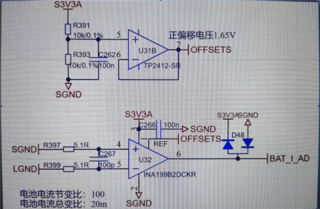
Customer application schematic is like this.  The REF pin add a positive voltage 1.65V.
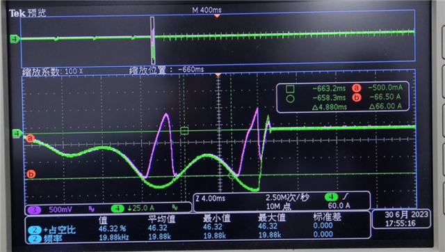
The waveform is like this(Green waveform is the Current from SGND to LGND. Blue waveform is OUT pin voltage). The question is that blue waveform have an area of which the amplitude is over the REF, which means current position is reverse. But the current waveform is still from SGND to LGND. What's the problem here? 
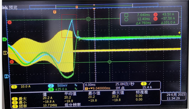
  • We take an another test. Once the current(green waveform) is up to a specific value, the INA199 output(red waveform) is abnormal.  

  • Hi Dillen,

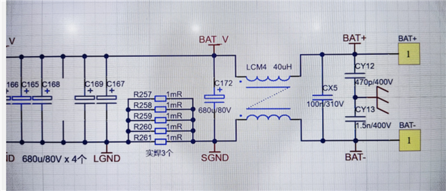
    Can you confirm if the total shunt resistance is 0.2mOhm, and the current value at which INA199 output becomes abnormal is 66A?

    I see two symbols for SGND, are they the same net? Is LGND only connected to INA199 input?

    What is the yellow waveform in the first scope picture?

    The common mode input range of INA199 is -0.1V to 26V, It is a good idea to make sure the spec is not violated.

    Regards, Guang 

  • Hi, Guang Zhou,

    1.shunt resistance is 0.2mOhm

    2.current up to 66A, then INA199 becomes abnormal

    3. two symbols For SGND is the same. LGND only commected to INA199 input

    4.  yellow waveform is LLC resonance current, not related to this question.

    5. It is hard to directly measure CM input. IN- and IN+ voltage is very low. The measure noise is very high.


  • Hi Dillen,

    Thank you for the confirmation, I don’t see anything wrong with the operating condition then.

    Have this phenomenon been observed on multiple boards? Does it happen on brand new builds, or only happens after a while? You might want to look at the possibility of a faulty unit.

    Regards, Guang