This thread has been locked.

If you have a related question, please click the "Ask a related question" button in the top right corner. The newly created question will be automatically linked to this question.

XTR116: Producing a 4-20mA current loop alongside an MCP4921 DAC

Part Number: XTR116
Other Parts Discussed in Thread: MIKROELEKTRONIKA

Hi

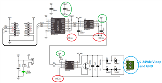
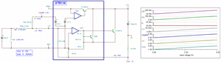
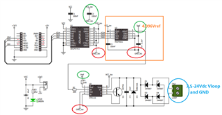
I recently purchased a MikroElektronika 4-20mA T Click MCU Add On Board MIKROE-1296 for an application that I need for a project at work, which has a 24V source connected to the screw terminals, and tested connecting to it with both a voltage supply and a fluke loop calibrator. This board has an MCP4921 DAC which I have programmed via SPI to give out a voltage range of 0-4.095V. But the board (or technically the XTR116) will not output a current of less than 4.4mA.

I have tested this board with both setting it to its lowest value and looping through the values 0-4095 and back again but it will not go below 4.4mA in any of these cases. Additionally, when programming the board to loop through its range, the board has this weird behaviour where when the current comes close to 4.4mA it slowly changes before speeding up again, despite the voltage changing at the same rate.

I have checked if there was an error with the MCP4921 not using the whole voltage range by measuring its output which in turn could affect how much current I can get out of the XTR116, but the MCP4921 uses the whole voltage range.

I have read on various forums that this may perhaps have something to do with the current draw of the XTR116. Any solutions on how I can make the board use the 4-20mA span? Is there anything fundamentally wrong with the design they have implemented?

Below is the schematic for the 4-20mA board that I have tested

  • Hi Alexander,

    but it will not go below 4.4mA in any of these cases. Additionally, when programming the board to loop through its range, the board has this weird behaviour where when the current comes close to 4.4mA
    Any solutions on how I can make the board use the 4-20mA span? Is there anything fundamentally wrong with the design they have implemented?

    Did you read the the EVM's user guide or manual? I have not read the user guide, but the EVM should work. 

    XTR116 is 2-wire current loop V/I transmitter, and the input voltage, Vin, is likely from 0-5Vdc and convert it to 4-20mA proportionally. The XTR116's current will not exceed 3.7mA when there is Vin = 0V ( pin8 on U2 w.r.t. GND_iso node. GND_iso or pin3 of XTR116 node is floating. So the lowest measured current in 4.4mA is likely a measurement errors. It should be measured at 4.0mA when Vin = 0V (if Vin is shorted to GND_iso pin).  

    On the Vloop side, the XTR116 should be powered from 7.5Vdc - 24Vdc on Vloop side. Vloop's GND is different reference GND from GND_iso, shall not be connected to each other. 

    Enclosed are the XTR116 Datasheet, application note and simulation. If you have additional questions, please let me know. 

    https://www.ti.com/lit/ug/slau526/slau526.pdf?ts=1688574667188&ref_url=https%253A%252F%252Fwww.google.com%252F

    https://www.ti.com/lit/ds/symlink/xtr116.pdf?ts=1688542909484&ref_url=https%253A%252F%252Fwww.ti.com%252Fproduct%252FXTR116%252Fpart-details%252FXTR116U

    XTR116 07052023.TSC

    If you have other questions, please let me know. 

    Best,

    Raymond

  • Hi

    Thanks for the response.

    All the information I have about this board are the descriptions and files available at this link: MikroElektronika 4-20mA T Click MCU Add On Board MIKROE-1296 | RS (rs-online.com). Despite having contacted RS for more information about the product.

    Additionally, from what I've read in the datasheet of the DAC, there is not too much too it than communicating to it via SPI and ensuring that you have the desired voltage value on its output. Which, as I mentioned, I have both managed to have it output a constant value and loop through the entire voltage range. 

    The output voltage of the DAC was measured by connecting to VOUT and GND_iso, while the current was measured connecting a multimeter in series with one of the screw terminals. I am aware that reference GND and GND_iso should not be connected to each other, and to my knowledge I did not do so either. 

    So I am not quite sure what is wrong. The only thing I can think of as evident after I saw your simulation is that the default EVM provided by MikroElektronika does not have a resistor (Ros) between VREF and Iin. Would this perhaps fix the issue?

    Best regards,

    Alexander

  • Hi Alexander,

    Would this perhaps fix the issue?

    The Vref = 4.096 is fed into DAC, which it implies that DAC's max. output voltage is from 0 to 4.096Vdc w.r.t. Iret or GND_iso. 

    Please confirm the MCP4921, U2's output voltage is in the range mentioned above. 

    If this is the case, then Viso shown in the simulation is ranged from 0V to 4.096Vdc, and Iout will be converted from ~0mA to 20.48mA. 

    XTR116 has a current gain in 100A/A, When Viso = 4.096V, I_in = 4.096V/20k = 0.2048mA, Iout = 100*0.2048mA = 20.48mA. 

    XTR116 07062023 Mikroe.TSC

    If your requirements are 4-20mA, then you would need to add Ros = 102.4kΩ, which it generates I_in = 40uA --> Iout - 4mA (when Viso = 0V).  

    I have not gone through the 3rd party user guide, but this is how XTR116 should work as simulated.  

    If you have other questions, please let me know. 

    Best,

    Raymond

  • The current draw of the XTR and the MCP are about 0.2 mA each. The ADuM can draw much more, depending on the frequency. Is the SPI interface idle while you are measuring?

    Please check the voltage drop over R2 (1 V should correspond to 5 mA), and that VCC_iso is 5 V relative to GND_iso. (If VCC_iso drops, then this shows that some components draws too much current.)

  • Hi Alexander,

    I am going to close this inquiry. 

    If you have other questions, please let us know. 

    Best,

    Raymond