This thread has been locked.

If you have a related question, please click the "Ask a related question" button in the top right corner. The newly created question will be automatically linked to this question.

OPA4743: Bode plot and pole point of OPA4743

Part Number: OPA4743
Other Parts Discussed in Thread: TINA-TI, TLV9164

Hi team,

Hope you have a good day!

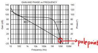
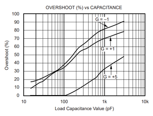
This is Jerry, currently my customer is using OPA4743 in their new design, and they want to know how we test the bode plot and why there is a pole point at 10MHz. They also want to know the open loop transfer function of OPA4743. This may help them to analyze how much capacitive load can be connected to OPA4743 and make sure stability at the same time.

Pls feel free to let me know if you have any questions. Thanks a lot.

  • Hey Jerry,

    This can be found with the overshoot vs capacitive load drive in the datasheet.

    You can calculate phase margin from this using the overshoot vs phase margin calculator in the analog engineers calculator. https://www.ti.com/tool/ANALOG-ENGINEER-CALC

    Once you are past 23% overshoot, you are below 45 degrees of phase margin. So in a gain of -1 or 1, your upper limit is around 40pF. In a gain of 5, you can put roughly 700pF.

    Best,
    Jerry

  • Hi Jerry,

    Very appreciate for your answer!

    Furthermore, could we provide the below materials to customer since it may difficult for customers to download and install software due to their company's policy.

    1.  How we test the bode plot;

    2.  Why there is a pole point at 10MHz of OPA4743;

    3.  The open loop transfer function of OPA4743.

    Thanks a lot.

  • Hey Jerry,

    The bode plot is tested with a gain/phase analyzer and a special high speed servo loop. It is complex to measure.

    Typically the amplifier design philosophy is to have a pole at least one decade after UGBW. This may be an artifact of parasitic capacitance on the test setup. Generally on the datasheet, the main concern is accurate measurement within UGBW, as measurement outside of UGBW is outside of the frequency of interest.

    The customer should not be using the transfer function of the amplifier to calculate cap load drive. This is not something that is generally provided.

    Best,
    Jerry

  • Hi Jerry,

    Very appreciate for your support!

    Furthermore, I use TINA-TI to build a simulation model for customers. It seems that the output voltage is not stable but the value of Y-axis keeps 3.00V. Could you help to explain the reason.

    Thanks a lot!

  • Hey Jerry, 

    The isolation resistor is placed incorrectly. I recommend implementing it like this: 

    We have existing TIPL training for Stability here: https://www.ti.com/video/series/ti-precision-labs-op-amps.html

    The snippet above is from Stability 5 - "Capacitive Loads" 

    I also recommend that since this is a new design the part number be changed to the new version, TLV9164: 

    All the best,
    Carolina