This thread has been locked.

If you have a related question, please click the "Ask a related question" button in the top right corner. The newly created question will be automatically linked to this question.

TLV4021: Reference Precision

Part Number: TLV4021

Hi

We're about to use TLV4021R1YKAR in one of our new designs.

I'm struggling to interpret the precision of the device in terms of positive- and negative-going input threshold.

In the datasheet chapter 6.5 the positive-going input threshold is 1.188V to 1.212 V over the full temperature range for Vs = 1.8 V. 

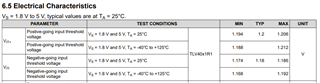
However, in the typical characteristics in chapter 7 we find the following graphs. The top left graph shows that the positive-going threshold in function of the temperature and also for different supply voltage is very precise and does not exceed 1.1988 to 1.2003 V in any case. Also the top right graph shows, that the threshold is very precise around 1.2V with a big number of tested devices. 

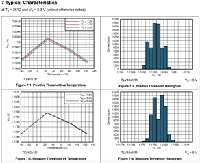
What's the tolerance of the positive-going threshold? What's the difference of the table in 6.5 and the figures in chapter 7? Why do the values differ? Same questions apply to the negative-going threshold.

Thanks and best regards, 

Martin

  • The minimum/maximum values in the electrical characteristics table are guaranteed, under all circumstances. The typical characteristics are based on a single experiment, and are not guaranteed.

  • Thanks for your reply. That was my understanding so far.

    But still I think it's misleading. We have Figure 7-1 showing the full temperature range. The influence of the temperature on the VIT+ threshold is minimal compared to the tolerance given in the electrical characteristics. 
    Also Figure 7-2 shows VIT+ threshold at room temperature for around 80k pieces (so not a single experiment anymore) being far more precise than the tolerance given in the electrical characteristics.

  • Hi Martin,

    Thank you for your question.

    I think the main cause of confusion stems from the assumption that the electrical characteristics in 6.5 are solely determined by the data presented on 7.

    We see that in 7-2, all of the devices tested are binned between 1.1992V and 1.2007V, so your assumption would be that those values should be our reported minimum and maximum for this device. However, our test and validation engineers run different tests and gather data that are not presented on the datasheet. We use that data to guard band our specifications such that you will most likely not find a device that approaches and definitely not exceed the minimum and maximum (at test conditions).

    In 7-1, you see the average threshold voltages of multiple devices tested over the temperature range. The same reasoning applies, where other data is gathered and the specifications are guard banded such that the device would not exceed minimum and maximum when operating in test conditions.

    Precision near the reported typical value is expected, since the typical value is the value that you may expect a majority of the devices to be around.

    In response to the tolerance of the positive-going threshold, you can use the minimum and maximum in the electrical characteristics in 6.5 as your worst-case values.