This thread has been locked.

If you have a related question, please click the "Ask a related question" button in the top right corner. The newly created question will be automatically linked to this question.

BUF802: BUF802 propagation delay

Part Number: BUF802
Other Parts Discussed in Thread: TIOS101, UCC27517,

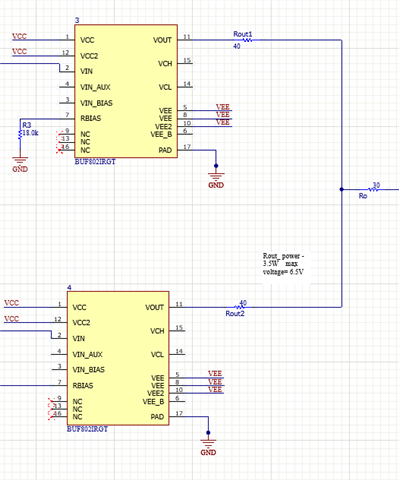
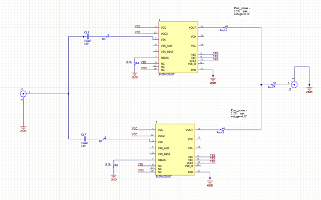
I am using two BUF802s in parallel as my output driver as shown below.

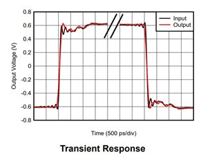
The input to my BUF802s is a square wave.

How to determine how much Propagation Delay is the buffer adding to the two signals? Couldn't find anything specific regarding the delay on the datasheet.

  • Figures 6-9 and 6-10 imply that the propagation delay is zero. Apparently, the offset between input and output was removed. Anyway, the frequency response graphs show that it is at most a few nanoseconds.

    The BUF802 is designed for analog signals. If your square wave uses two fixed voltages, then consider using an I/O driver like the TIOS101 or a gate driver like the UCC27517.

  • Can you pls explain how are you calculating the delay from the frequency response graphs? 

    Also my square wave has frequency of 500MHz. UCC27517 has pretty large rise-fall times.

  • There is no precise calculation. If the delay were larger than a few ns, then it would not possible for the buffer to output signals near the GHz range.

  • Hi Clemens,

    Thanks for your reply.
    Can you pls say how to justify that a for a given input both the buffers will add exactly the same amount of delay? 

    Like in the structure below, I have given an input of 500MHz square wave. Can I say that both the buffers will add exactly the same amount of delay at a given time? 

  • Hello Debasmita,

    I believe you asked a separate question/post  already for this thread response.  If you are experiencing a high priority project concern for a customer account, please provide a timeline and details on your customer's circuit/application outside of the BUF802 subcircuit which was shared.

    It appears you are using the two BUF802s in parallel to boost drive strength of the buffer; the customer is concerned about distortion or uneven signal propagation at 500MHz for their square wave.  Has the customer performed any simulation or in-lab board tests to showcase the potential need for research on BUF802 propagation delay?

    Please elaborate if possible on the customer need and circuit use.  If you would prefer, you may reply to this thread and I can close the other question you asked about part-to-part skew:

    https://e2e.ti.com/support/amplifiers-group/amplifiers/f/amplifiers-forum/1248998/buf802-part-to-part-skew

    Best,

    Alec

  • Thank you Alec

    Yes you can close the other question.

    Customer has performed a very crude test in the lab by using SMA couplers to couple the outputs of the two buffer EVMs.

    The customer wants to make a high frequency square wave generator. So they wanted to drive the output signal using this driver.

  • Hello Debasmita,

    Has your customer encountered distortion or signal loss on their signal chain?  If they have a figure of merit or numeric target for performance I can use a singular BUF802RGTEVM in the lab to examine propagation delay at 500MHz. 

    Could you please share the following details?

    - VCC and VEE in the schematic diagram

    - Voltage levels and any other details you have on square wave 500MHz input, such as duty cycle

    - Explain if the 6.5V voltage is the measured/simulated output voltage at Rout2, with Rout2_power = 3.5mW.

    - What is the performance target for the customer?  Do they have an acceptable amount of delay?  An acceptable amount of distortion?

    Generally, as the BUF802 is an open-loop buffer with zero feedback path, the propagation delay is only the time it takes for the input signal to make it through the network of transistors to the output.  With a Gain-Bandwidth Product of 3.1GHz, there is a fair assurance that the BUF802 will not be the limiting/slow factor in the total propagation delay of the signal chain.

    Once you share details, I can provide better thoughts and go into the lab if measurement is requested.  However, I cannot go measure in the lab if I do not have target or preferred values to be looking for.  Clemens' earlier suggestion of UCC27517 had rise and fall times which were too large, as stated by your customer.  Please assist with providing the information I requested.

    Thank you for your time.

    Best,

    Alec

  • Hi Alec,

    Thank you for your response.

    The VCC and VEE used are 6.5V. 6.5V measurement is at Rout2. 

    The square wave has a rise time of 200ps at 500MHz. 

    I have tested the EVM at these conditions at lab and got a propagation delay of 1.6ns. But how shall I be confirmed that both the buffers will give me the exact same delay at any given time?

    Customer wants distortion less output. However a few nano seconds of delay is acceptable.

  • Hello Debasmita,

       Thank you for the additional information and sharing the results of the EVM test. If the critical spec is delay between buffers, and a propagation delay of the EVM test is acceptable, then, I agree with Alec that the main contributing factors would be the cabling/board setups symmetry rather than the buffer. 

       If the BUF802 is performing in the linear region (within recommended specs listed in the datasheet), then the device will not affect a delay measured within a few nano seconds. Below is measured data that shows input/output follow within a few ps which is much lower than measured signal chain of 1.6ns:

    Thank you,
    Sima