This thread has been locked.

If you have a related question, please click the "Ask a related question" button in the top right corner. The newly created question will be automatically linked to this question.

MF10-N: BPF doesn't work as designed

Part Number: MF10-N
Other Parts Discussed in Thread: LMF100

Hi,

MF10-N BPF doesn't work according to the design.  Help please.
The following schematic is it:

This is an 8th order chebyshev band-pass filter, in which every stage
runs in the mode 3 with the 100:1 clock, and I'm sure I designed it so
as to run with the 0dB gain in the pass-band. The clock supplied is
typically 240kHz, the duty ratio is exactly 50% because of 1/2 divider.
The bode plots shown there are the ones that the LTspice calculated
using the spice model LTC1060, as known as mostly compatible with
MF10-N.

However, the actual gain is too large and the pass-band-width looks
too narrow.  The 1st stage, i.e., "IN" through "TP1", behaves especially
funny.  The Hobp is calculated as R3*/R1*, so the peak gain should be
near to 180k/150k in the 1st stage, but actually it is too peaky as
shown below:

Does anyone know what I failed?

Thanks in advance.
Regards,

  • Hello,

    In "Mode 3", the center frequency of the low-pass and band-pass 2nd order functions can be either directly dependent on the clock frequency or can depend on both clock frequency and external resistor ratios. The center frequency of the notch and all-pass functions is directly dependent on the clock frequency, while the high-pass center frequency depends on both resistor ratio and clock.

    At first sight nothing stands out in your schematic, but since the filter Q and gain are determined by external resistors, make sure that these values are set correctly in your board for your desired filter response.

    In order to help further, it might also be helpful if you could share some additional information:

    • Would you also be able to share the characteristics of your Input and CLK?
    • What is your measurement setup?
  • Hi,
    Thank you for following me up.

    Here are the tentative parameters I brought in initially:

    Stage   Hobp    f0[kHz]  Q
    -----------------------------
      1     1.2     2.5     7.18
      2     1.2     2.282   7.18
      3     4.02    2.67    17.4
      4     4.02    2.15    17.4

    The values are I got from a certain web-based analog filter tool as
    for building a narrow and sharp, and low ripple chebyshev BPF.

    The parameters used at present are slightly modified (so as to
    make the response viewed flat and bilaterally symmetric in LTspice)
    as follows:

    Stage   Hobp    f0[kHz] Q
    ------------------------------
      1     1.200   2.500   7.186
      2     1.200   2.289   7.171
      3     3.607   2.675  17.437
      4     3.830   2.150  17.411

    Note that f0's value is meant for the case where the clock is 240kHz.

    We've verified that all the resistor values are as designed.
    Though, the actual response is not resemble with designed.

    The clock is fed from a C-MOS flip-flop (74LVC1G80, 3.3V) that divides
    by 2 a XTAL based programmable clock generator. When we measured
    an analog signal responce, we used an output of a wave-form generator
    and an audio level meter.

    Regards,

  • Hello Yamaoka-san,

    Thank you for sharing the details of your MF10-N bandpass filter setup.

    I do want to mention, our team structure has evolved and our dedicated experts for switched capacitor filters like the MF10-N have moved on. However, we will do our best to support your inquiry and I am reaching out to other teams for assistance. In the meantime, I found a DOS design tool (FILDES) and a book on switched capacitor filters (Switched Capacitor Filter Handbook - National Semiconductor - April 1985).

    http://www.mhhe.com/engcs/electrical/franco3/student/download.mhtml (3rd Party Site)
    FILDES Design Programhttp://www.mhhe.com/engcs/electrical/franco3/filedes/FILDES.zip

    Disclaimer: note we no longer maintain that design program ourselves, so downloading and using the program is at your own risk.

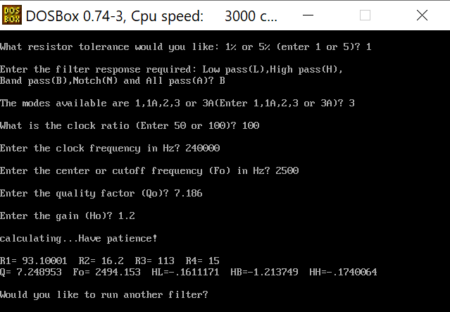
    The MF10RES Design Program is a tool that could help you calculate the optimal resistor values for your MF10-N bandpass filter setup. By inputting the desired filter specifications and component values, the program can generate a set of recommended resistor values that should provide the best performance.

    I was able to run the MF10RES Design Program on Windows 11 using a DOS emulator (e.g. DOSBox). Using some of the numbers you shared, I got a set of resistor values that are different from those in your schematic. It might be worth trying the resistor values suggested by the MF10RES design program to see if they improve performance.

    The quality of the clock signal can significantly affect the Q of the MF10-N’s filter functions. As explained in the MF10-N datasheet, the center frequency of various functions depends on the clock frequency. If the clock signal is unstable or has significant jitter, this could impact the center frequency and thus the Q.

    It would be helpful if you could verify the stability of your clock signal. Is the frequency steady? Is the duty cycle precise? Are there any distortions in the waveform? An oscilloscope plot for the CLK and input could be really useful in verifying these details. Additionally, while a 3.3V signal meets the minimum logic thresholds, it might be worthwhile trying to use a 5V clock signal to see if it improves performance.

    Lastly, the layout of the PCB is like the foundation of a building – it’s critical for the overall performance of the circuit. Parasitic capacitance (even capacitance coming from flux) or inductance can affect the effective values of components in the circuit, potentially impacting the Q. Could you share some details about your PCB layout, including grounding, shielding, and routing practices? It would also be helpful to know whether the PCB has gone through cleaning after assembly to remove any residual flux that could impact performance.

    Thank you for your patience and efforts in troubleshooting this issue. Please feel free to share any additional details or observations.

    Best Regards, 
    Victor Salomon

  • Thanks a lot for many suggestions[1].
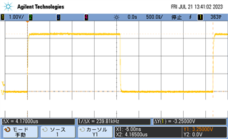
    A clock waveform is below:

    There is no jitter as far as we can see.  The 3.3V logic is safe I believed
    since MF10-N allows the TTL level (0.8V-2.0V) logic.

    We have two identical boards, and verified the responses of the BPF 1st
    stages look identical, that is, too peakey.  In addition, the 2nd stage
    (TP1 through U123[19]) is also peakey similarly to the 1st satge.
    However, the 3rd and the 4th stages (U124) look normal (though it olly
    means the gain at 2.4kHz of those stages are almost those of  designed[2]).

    [1] Unfortunately, FILDES didn't work probably due to the filsyp.exe file
    in the zip archive to have been corrupted; the unzip command said:

    inflating: filsyp.exe    bad CRC eff42782  (should be c1a639f5)

    FYI, I couldn't download FILDES.zip from www.mhhe.com in Japan, so
    I tried it in a Linux machine that I rent personally in US and succeeded.

    [2] As I'm working remotely now, I have to ask a coworker to do something
    if necessary. So, I'd like to ask him to measure the responses totally and
    individually after having solved the issue that the 1st stage is too peaky.

    Regards,

  • Well, isn't there an upper limit for the resistor values?
    Whereas the MF10-N manual only mentions resistor ratio, a 100Meg-ohm
    resistor is too large, isn't it?
    Aren't the resistor values used in our design too large (especially for the 1st
    and the 2nd stages)?

    The LTC1060 spice model works on LTspice no matter what ultra-high resistors
    are given, though.

  • Solved.

    First we tried replacing U123 from MF10-N to LTC1060;  then the filter
    gains turned lower a bit but were still peaky.   Second we tried changing
    the resistor values lower while keeping the ratios;   thereupon the total
    filter characteristics almost matched to that of the LTspice simulation.
    Here are the revised schematic and the simulation:


    Therefore there is probably an upper limit for the resistor values.
    Though the manual doesn't mention what the upper limit is, we know
    the lower limit:


    So, a better way to design the resistor values would be to decide the value
    of the resistor, that is the smallest of R2, R3, and R4, to 6~10k-ohm.
    Probably the schematic shown above will work with MF10-N as U123 as
    well (not tested yet though).

    Thanks.

  • Good afternoon, Mr. Salomon,
    looking for a solution I found this forum and your entry. I would like to lay out a high pass filter with the LMF100. I would like to use the DOS program FILDES for this. Unfortunately, as already written the download is corrupted. Is there a possibility that you provide me or the community here in the forum a link to download an executable version ? Thanks in advance.
    If this post is wrong for my letter, I apologize. I do not have much experience on these internet platforms.
    Many greetings
    Ralf

  • Hello Ralf,

    I am still able to download and open the DOS program, however, this is currently hosted in a 3rd party site, which isn't supported by Texas Instruments.

    I would recommend reaching out to the owner of the site where the program is hosted, which can be found here:
    http://www.mhhe.com/engcs/electrical/franco3/email_author.mhtml