This thread has been locked.

If you have a related question, please click the "Ask a related question" button in the top right corner. The newly created question will be automatically linked to this question.

LM311: Problems with a simulation of a bipolar window comparator with hysteresis

Part Number: LM311
Other Parts Discussed in Thread: LM111, TINA-TI,

Hello,

I would like to build a bipolar window comparator with hysteresis. The input signal is a sinus waveform, 5 Hz and 8 V peak. Here is my simulation:
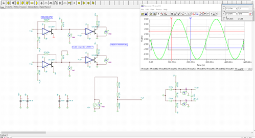
The simulation is not working properly if the input sinus of U1 and U2 is +- 8V and the supply voltage is +-8V. So I divided the input sinus by the factor 4/3 to +- 6V (would be the worst case in the real application). The problem I have is, that the comparators on the negative and positive side are not working symmetric even if the voltage dividers are at the same voltage levels (proportions). The hysteresis and switching point from U2 is determined by: R4, R15 and +1.6V, +5V and GND. From U1 it is determined by R7, R5 and -1.6V, -5V and GND. I would expect that it should behave symmetric. I would like to have the switching points at +-1.9 V (high level) and +-1.55 V (low level). U3 is just a level shifter and U4 is an inverter, the signal from there would go directly to a LED.

If I do the same simulation in LTS with a comparator with a similar internal construction it is symmetric:
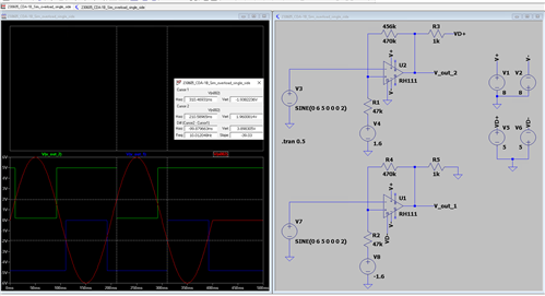
Someone has a hint what's wrong here?

Kind regards,

HD

  • Hello Heidelberg,

    The LM111 is not a rail-to-rail input. The LM111 valid input ranges from 500mV above V- to 1.5V below V+.

    So with a ±8V supply, the valid input range would be -7.5 to +6.5V. So the full ±8V signal would violate the input range.

    The TINA-TI LM111 model has a feature in which the output is forced to mid-supply when the input range is violated. This is mentioned in the header.

    The LT Spice RH111 model does NOT have this feature - so it seems "normal".

    So the "feature" may be why you are seeing "strange" behavior in the outputs.

  • That is okey for me. Because of that I implemented the voltage divider from +-8 to +-6V. The thing I don't understand is the unsymmetrical behavior of the two comparators even if the voltages and resistor values are the same. You can see it in the pictures at the cursor positions. In LTC it is very symmetric and in TINA with the LM311 (which I want to use) not... 

  • And another point would be: why the high and low threshold are different in LTC and TINA even if the voltage values and resistor values are the same? The voltage divider from the output to +- 1.6 V is the same.

  • Hello Heidelberg,

    It may be artifact of the TINA simulator. You may need to adjust the max time step to be 1/1000 of how long your transient window is. You can do this under Analysis -> Set Analysis Parameters. Under "TR maximum time step", you would set for .5ms if your window is 500ms

  • Hello Chi Nguyen1,

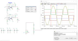
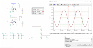
    I did it and it is a little bit more symmetric but not perfect:

    But I am not able to adjust the resistors to get a high and low threshold of 1.9 to 1.6 Volts. At the positive side we have a voltage divider from 5V over R4 and R15 to 1.6V at the low state of LM311 and at the high state 0V over R4 and R15 to 1.6V (when R19 << R4, R19 can be neglected). In the low state I can calculate the voltage divider by hand to get 1.9 Volts in the middle of R4 (470k) and R15 (47k). For the high state the middle potential should be around 1.45 Volts. Is the simulation or my calculation incorrect? Is it possible to adjust the simulation to a high threshold of 1.9 V and a low threshold of something close to 1.6V?

  • My bad, I have to take the correct input signal:

    Thank you for your help!