- Ask a related questionWhat is a related question?A related question is a question created from another question. When the related question is created, it will be automatically linked to the original question.
This thread has been locked.
If you have a related question, please click the "Ask a related question" button in the top right corner. The newly created question will be automatically linked to this question.
Hi Team,
For INA317IDGKT is having dual supply range is +/- 2.75 V is the max range as per datasheet power supply recommendations.
But I have found one board with INA317 IDGKT with +/- 5V , it means Positive supply 5V (at Pin 7), Negative supply -5V (at Pin4) its well working, I am surprising that why beyond the rated limits also IC working fine.
Why its not destroyed.
Thanks & Regards,
Siva
Voltages below 5.5 V are guaranteed to work. There is no guarantee for voltages above 5.5 V.
Voltages above the absolute maximum rating of 7 V can damage the device. What form this damage takes cannot be specified, but 10 V is certain to degrade it.
Hi Siva,
Why its not destroyed.
Please follow the datasheet's recommendation. The specified performance is guaranteed under the recommend operating condition as Clemens indicated.
I am sure that there may be some damaged and/or degradation at IC level, where one may see the damage under SEM or other failure tool analysis. On the surface, the IC seems to be "working" from a few tests you conducted and concluded. We do not know how long the part is able to operate "properly" under the EOS conditions at the elevated temperature.
The IC design comes with certain levels of electrical and/or thermal design margins (over design requirements). INA317 IDGKT package may have better electrical design margin than specified, and is capable to withstand higher EOS condition to protect itself.
It is good to know that INA317 IC has rugged design, but it does not mean that the part should be operated outside the recommended operating conditions. In other words, you should feel confident that the INA317 instrumentation amplifier meets and exceeds the specified reliability requirements.
Best,
Raymond
Thanks for your response...
I will change its supply range to +/- 2.5V from +/- 5 V , Bcz I have ambiguity such that its well working even with out of boundary supply range also ,
Secondly I wanted to confirm one more thing, is it able to sense 1mV difference like in Vin- ( 2 pin) voltage is 2.5VDC, on Vin+ (3 pin) voltage is 2.501DC.
Is INA317 able to sense 1mV difference & amplifies the input.
Thanks & Reagrds,
Raj
Hi Raj,
Is INA317 able to sense 1mV difference & amplifies the input.
Yes, INA317 would work with differential of 1mV at input or less and gain it up via the instrumentation amplifier.
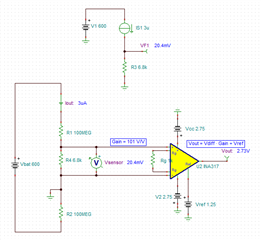
Below is a simulated example of 5Vdc single supply. INA317 can also work with the dual supply rails up to ±2.75Vdc. I need the design requirements to assist you.

INA317 Strain Gauge 07242023.TSC
Best,
Raymond
Hi,
Thank u for your response, My application is insulation resistance detection in electric vehicle.
To know the IMD performance, wantedly I am keeping known resistance 200 ME across 600V DC supply, that means 100ME Positive supply w.r. to Earth, 100ME Negative supply w. r. to Earth.3 Micro amp is branch current, across 6.8K I am sensing the drop via INA317 & Processing further & declaring the faults
Thanks & Regards,
Siva
Hi Raj,
Could you see if I understand the analog input configuration correctly? I want to make sure where 6.8kohm is branched to. Please correct the drawing, if this is not correct.
Also, what is the response time for the interrupter? Are you designing a ground fault circuit interrupter for 600Vdc voltage?

Best,
Raymond