Because of the holidays, TI E2E™ design support forum responses will be delayed from Dec. 25 through Jan. 2. Thank you for your patience.

This thread has been locked.

If you have a related question, please click the "Ask a related question" button in the top right corner. The newly created question will be automatically linked to this question.

OPA607: OPA607 to configure the receiving portion of the transducer

Guru 10050 points
Part Number: OPA607
Other Parts Discussed in Thread: OPA837, TIDA-01565, OPA2607, ADS2806, TS5A9411, OPA836, OPA838

Hi,

I am considering using an OPA607 to configure the receiving portion of the transducer.
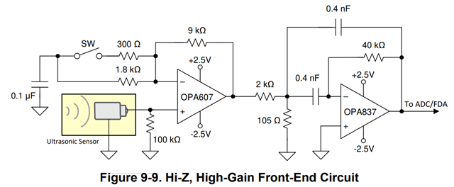
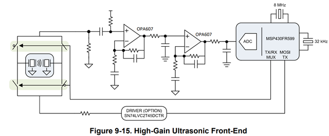
Figure 9-9 and Figure 9-15 in the datasheet describe the receiving circuit from the ultrasonic sensor, respectively.

1) Could you please tell me the difference in the application of the circuit configuration in Figure 9-9 and Figure 9-15?
  

2) I am considering a configuration (discrete) where the transducer is driven by 350 kHz PWM pulses and an amplifier is used for it's receiving circuit. Please let me know if you have any helpful information or recommendations for a Device. Also, I need a sampling rate of 32 MHz or higher for the ADC in the latter stage. Are there any products that can communicate with the C2000?

Thanks,

Conor

  • Hello Conor,

    1. The first figure shows the front-end receiving circuit using the OPA607 for high input impedance input and the following it with the OPA837 as a variable gain mux / PGA and bandpass filter as shown in reference design TIDA-01565.

      The second figure shows a circuit that can switch between receiving and transmitting for the same type of application. The OPAx607 enable a higher gain design combined as an ADC drive stage, thereby reducing component count via using only one device: OPA2607.

    2. What is your gain range requirements, voltage supplies, and is the ADC differential or single ended input? Is this referred ADC internal to the C2000? 

    Thank you,

    Sima

  • Hi Sima,

    Thank you for your help. I understand about Q1.
    Regarding Q2, the ADC specifications, the C2000's internal ADC does not meet the sampling rate (32 MHz or higher).
    Gain and supply voltage are not fixed. If I configure OPA607 with 2 stages, does it need to be a differential ADC? 
    Also, does the following configuration also require 3 channels of multiplexers?

    Thanks,

    Conor

  • My apologies. I hit Resolved by mistake.

  • Hello Conor, 

      No worries, we can continue discussion on this thread.

      Therefore, that would mean you would be using an external ADC with a higher sampling rate. If the ADC is not differential, then you do not need a fully differential amplifier, and the OPA607 as shown in the earlier figures can interface with a single-ended input ADC. 

      I believe the figure has two channel switches with MOSI acting as an enable/disable pin. If you are only configuring the circuit for receiving portion, this section of the figure won't be necessary.

      For ADC recommendations, please create a new thread linked under our high speed ADC e2e forum. Easiest way, would be use the ask a related question yellow button on top right of this thread, and you may use ADS2806 as an example device to link. 

      Feel free to continue asking about high speed amplifiers and ultrasonic applications in this thread. 

    Thank you!
    Sima 

  • Hi Sima,

    Thanks for the answer.
    I see in the internal circuit of the USS of MSP430, there is an amplifier filter circuit on the receiving side, is the first stage of OPA607 used for such purpose? Or simply to increase amplification? Also, am I right in understanding that two multiplexers are needed in this case, since the same MCU is used to control both the transmitter and receiver?

    Thanks,

    Conor

  • Hello Conor,

     An example discrete front-end to the MSP430 is shown below:

      This block diagram is from Ultrasonic Sensing Subsystem Reference Design which can be found at this link. The blue square shows the discrete front end which is external to the MSP. This block uses the TS5A9411 (single-pole double-throw (SPDT) analog switch) as the example MUX, and OPA836 or OPA838 as the example high-gain first stage which can be replaced with the OPA607. Internal to the MSP430 is a PGA (programmable gain amplifier) which provides the additional amplification from –6.5 dB to 30.8 dB. 

    Thank you,

    Sima