hi team,
Could you help work out a suitable solution to fit in below application?
Input signal: 10Hz PWM, voltage range from 0V to 18.5V
Output signal: logic low when VIL:0~2 V, logic high= VLH:4.2-18.5V

Regards,
Dongbao
This thread has been locked.
If you have a related question, please click the "Ask a related question" button in the top right corner. The newly created question will be automatically linked to this question.
hi team,
Could you help work out a suitable solution to fit in below application?
Input signal: 10Hz PWM, voltage range from 0V to 18.5V
Output signal: logic low when VIL:0~2 V, logic high= VLH:4.2-18.5V

Regards,
Dongbao
Hi Dongbao,
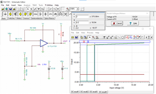
Looks like you found a good resource for your question. Below is a potential solution using a non-inverted configuration with 20V as your supply, reference, and pull-up voltages. The transfer curve is VIN+ versus VOUT, and shows your VIL and VLH switching points at 2V and 4.2V respectively. When VIN+ reaches 4.2V, this circuit outputs 18.94V. Your sinking current would be 2.45mA when VIN+ is 0V. Additionally, attached is the TINA setup for the circuit, as well as a hysteresis calculator if you would like to fine tune the circuit for your application. An example would be to increase the pull-up resistor to reduce power consumption, but this will also lower how strong your output is when reaching 4.2V. Let me know if you have any questions, I’d be happy to assist you further.
Best,
Michael

hi Michael,
Thanks so much for your help.
I just realize there are some challenge in real automotive design, pls suggest whether you have more elegant solution:
1. since MCU is 3.3V or 5V tolerance after the circuit, any way to get translate the 18.5v voltage to 3.3V/5V?
2. It's not easy to get a stable high voltage power supply (>12V), usually a boost might need to achieve a higher enough voltage saying 18.5V+ as the input signal comes from another ECU.
Regards,
Dongbao
Hi Michael,
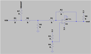
I have an idea that VCC, VPU and VIDV all use 3.3V, and add a voltage division circuit at the input end to make the input voltage range within the VCC range, as shown in the figure below. Is this design feasible?

Dongbao and Guisheng,
Thanks for the update. Yes, if the supply is 3.3V you'd need to divide the input signal. Here is what I got. Feel free to use this excel calculator to tweak your values as needed.