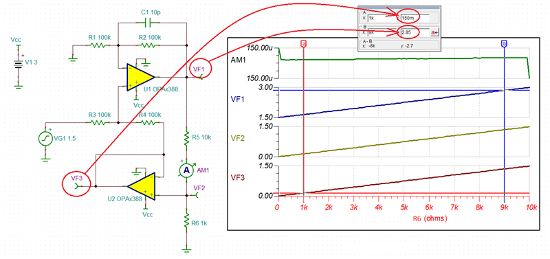
I'm currently designing a bioimpedance measurement device. I needed a constant current source for load excitation for which I chose the buffered enhanced Howland current topology. The output current requirement is under 300 uA. Input voltage is a sine wave of varying frequency with a 1.5 V dc offset. I am using the OPA2388 dual op amp IC with 0.05% resistors to make the current source. The supply voltage is 3 V and the ADG849 switch is used to switch between the load and a calibration resistor. The simulations I ran in LTspice work just fine but when I made the circuit, it does not perform as expected. According to the simulations, the output current should be constant up to 10 kΩ load. The output current is not constant when load resistance is changed (I used several discrete resistors well under 10 kΩ). Regardless of the load resistance, the output of the main opamp is always saturated to Vcc and there is a current flow even when the input pin Vin is left open.

I am afraid I might have overlooked some basic detail which is causing the issues. Can anyone suggest possible reasons why this circuit is not performing as expected or what areas I should investigate further? Any input is appreciated. The schematic (svg) file can be found here: https://ufile.io/vu7snvkj
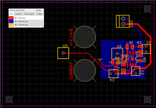
PS - The PCB is supposed to go on top of a pre-existing device hence the unusual layout. Also I hope posting Ltspice screenshots is not an issue...I've just been used to it.