This thread has been locked.

If you have a related question, please click the "Ask a related question" button in the top right corner. The newly created question will be automatically linked to this question.

LMP7707: The effect of the photodiode dark current and the op amp's own bias current on the op amp integration circuit

Part Number: LMP7707
Other Parts Discussed in Thread: IVC102, LMP7721, OPA328, OPA928, OPA3S328, OPA320, STRIKE

Hi

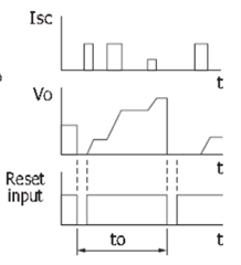
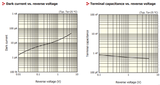
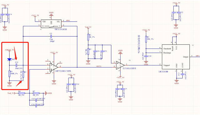
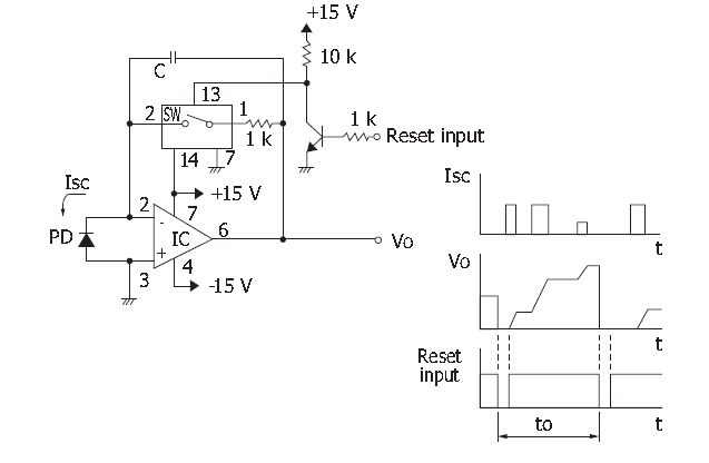
Using your  op amp LMP7707 to build an integral circuit to integrate the photodiode output current signal, PD is a photovoltaic mode zero-bias connection, the op amp power rail uses ±3V, the integration capacitor temporarily uses 10pF, Vo=Id×t/C, the basic principle is shown below:

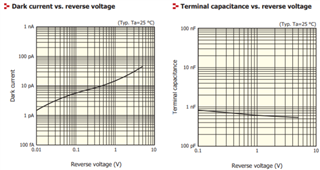
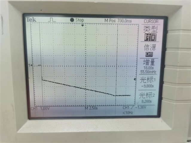
but now there is a problem, that is, in the case of photodiode shading, the integrator output quickly negative saturation, reaching the negative voltage rail, should be the dark current of the photodiode and the bias current of the op amp to charge the integral capacitor, the test is not connected to the photodiode, the op amp reverse input end is open, about 18s to the negative power rail, the calculation bias current is about 1pA:

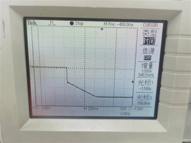
After connecting the photodiode to block the light, it takes about 750ms to reach the negative power rail, and the dark current plus bias current is calculated to be about 20pA:

1. Now that dark current and bias current are inherent characteristics, how can I minimize the impact of dark current and bias current on my output, so that the output reaches 0V, and able to integrate the photocurrent response normally?   

2. Slow charging after power-on, I can understand, what is the sharp drop of about 1.5V before charging ,Like in the picture ?

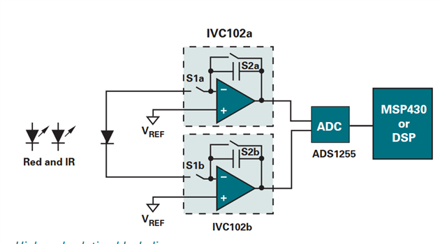
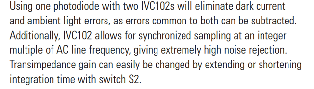
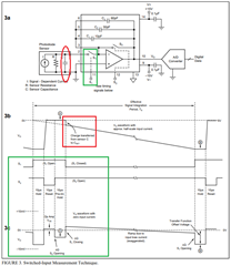
3. TI has a large technical document that mentions a circuit by using two IVC102, which is probably canceled out the dark current, but I didn't understand too much,  what is the principle?won't it have an impact on the normal photocurrent?

Looking forward to your answers

Best wishes

  • Hi Bing, 

    What is the photo sensing application? What is the "to" time period of the design requirements? Or it is triggered by an external circuit by Vo's voltage. Is this LIDAR application, where reflective current pulses are integrated? I was wondering why you choose integrated TIA vs. standard TIA or I-V converter.

    how can I minimize the impact of dark current and bias current on my output

    You may need to cancel the dark current and/or ambient light intensity errors in the circuit (as the IVC102 diagram indicated). Or you may consider AC coupled TIA. I need to know the sensing application. 

    2. Slow charging after power-on, I can understand, what is the sharp drop of about 1.5V before charging ,Like in the picture ?

    If the integrator is configured as shown on the left, my guess is that the capacitor is not fully discharged due to the RC time constant. It would be better to discharge the capacitor as shown in IVC102.

    what is the principle?won't it have an impact on the normal photocurrent?

    The working principle is to substrate the unwanted ambient light and dark current errors in the sensing or integration process. It looks like that the photodiode is operating in photovoltaic mode, which the output voltage is directly proportional to the amount of light falling on the photodiode. In Transimpedance mode, it converts the photocurrent of the incident light into the output voltage, which is more quantitative and precise method. For instance, in the spectrometer application, TIA or transimpedance mode is typically used, since the incident signal may be weak and higher gains are required. 

    So I need to know if you are only interested the current pulses or converts all the incident light current into voltage output. Ib of the selected op amp is important;  the Ib level should be negligible or very small comparing to the incident light signal and the errors should be small.   

    If you have other questions, please let me know. 

    Best,

    Raymond

  • Hi Raymond

    Thank you very much for your reply

    Not LIDAR , I used PD with scintillator for Radiation detection .I need to know the energy of radiating pulses over a period of time,so i choosed  the Integration circuit rather than TIA with resistor. For Weak pulses of current, (like 1nA,50μs),i have to use small capacitors.Therefore, dark currents and Ib cannot be ignored.By the way ,sharp drop of about 1.5V before charging ,i short the capacitor ,it did not improve.

    Regards

  • Hi Bing, 

    I see, you are talking about pyranometer. 

    https://www.deltaohm.com/wp-content/uploads/document/DeltaOHM_LPPYRA03_datasheet_ENG.pdf

    What type of integrator capacitor did you use in the circuit? please try polyester, which Mylar, polypropylene (PP) or polycarbonate capacitor, where these capacitor has dielectric absorption and low leakage currents. It will quickly discharge without significant charge retention. Polypropylene will be the best option for the integrator circuit application. 

    2. Slow charging after power-on, I can understand, what is the sharp drop of about 1.5V before charging ,Like in the picture ?

    I was thinking about capacitor residual charge retention issues, so please try out the PP film capacitor.

    Since I understand the application, how is the photodiode selected? Please send me a part number and I will take a look at the datasheet. 

    Are you working in visible, NIR region, UV-VIS-NIR or MIR region? If you are trying to detect sunlight radiation energy, let us say between 300nm - 2800nm region, did you have an optical filter to block the MIR and FIR light wavelength? I want to see the construction of PD and light absorption spectrum. The sharp drop could be due to unwanted scattered light, inner light reflection or something similar. the Inside of scintillator enclosure may require to coat with the light absorption material, say black paint. Did you use aperture in front of PD?

    Is the PD cooled or temperature compensated for the application? Did you consider to reverse voltage biasing on the PD per the measurement application?

    I am wondering all possible scenarios of your issues. If you have other questions, please let me know.

    Best,

    Raymond 

  • Hi Raymond 

    I used normal NPO capacitor,of course ,Polypropylene is better than it ,i will repalce it .

    i used a PD with scintillator ,there are two parts ,PD and a scintillator, like below,white part is scintillator

    www.hamamatsu.com.cn/.../s8193_kspd1042e.pdf

    This PD's spectral response range is 190~1000nm ,suitable for precision photometric determination in the UV to visible band.  Scintillator is a chemical compound. fluorescence is excited, when the ray irradiates the scintillator ,so PD can determine the fluorescence to detect radiation.

    PD is sensitive for visible,The photocurrent positively saturates the integrating circuit quickly,(Because photocurrent flows out of the op amp in photovoltaic mode,Vo=-I×t/C),that is why i make photodiode shaded(Shading with black tape).But it will be negatively saturates by dark current(maybe),that is my question.

    That is all,no cool,no temperature compensated.It's not that step yet.

    yes , next i consider to reverse voltage biasing on the PD and use AC couple ,use LMP7721 with 20fA Ib .Abandon photovoltaic mode(0 bias mode)

    Thank you again for your dedication to this issue.

    Best wishes

  • Hi Bing, 

    In the datasheet, there is approx. 1nf parasitic capacitance across the PD (without reverse biasing voltage). At the moment of S2 is closing, the residual parasitic capacitance (1nf) will charge the integrator capacitor (10pf) instantly and result in a dip on the scope shot. 

    Below is the timing diagram and you may need to implement two switches or discharge the PD parasitic capacitance by shorting the PD. If you use IVC02 IC, then this should not be an issue. 

    I will try to simulating the compensation of the dark current from the light measurement since I have the PD parameters. I will let you know. 

    BTW, your inquiry is not updating in our E2E forum for some reasons. I only got notice in my email when you replied.

    Best,

    Raymond  

  • Hi Bing, 

    I have looked into the subtraction of the PD's dark current and the ambient light below, here is my conclusion. 

    The dual IVC102 circuit will work if an application wants to subtract both integrated dark current and ambient light from the incident light, if the light source is pulse type or changing momentarily. Your application is different, where ambient light condition is integrated for a specific time period.    

    https://www.mouser.com/catalog/specsheets/tismedicalappsguide.pdf

    So here is what you may have to do. 

    It looks like the ceramic scintillator is directed mounted or glued on top of Si photodiode. If you are serious about making a precision light integration, you may have to mask the same Si photodiode (black tape) and integrate the dark current at the same time when scintillator/PD is integrating and make the measurement. You could mask off another scintillator/PD detector, but it may be costly. 

    So you would need two Si PDs (hopefully matching), and subtract dark current from other light measurement (may be eliminate Vos and Ib related errors as well). Since this is a linear system, you can subtract one from the PD's integrated dark current + influence parameters, and you should have much improved detection and measurement. 

    The ceramic scintillator light absorption spectrum resembles a photopic response filter (human eye response to light). So the scintillator crystal will emit fluorescence light when X-ray is excited it.

    Alternatively, you can do with single scintillator/PD, but you have to take a background (no light condition) for the integrated period and substrate the integrated dark current from the actual measurement via the CMU or op amp (consider this as software compensation). 

    There are other techniques to improve the measurement, such as,

    a. cool the photodiode at 5C range (also cool TIA op amp, if you cool PD )

    b. Reverse biase the PD

    c. use low noise zero-drift op amp (generally zero-drift op amp in TIA application is not recommended)

    LMP7721, OPA928, OPA328 or OPA3S328, OPA320 or LMP7707 may work well as the integrator TIA. Of course, IVC102 is designed for the application. 

    If you have other questions, please let me know. 

    Best,

    Raymond

  • Hi Raymond

    it's so kind of you ,thanks

    We have similar ideas,so I'm going to make a Evaluation board to verify three circuit  like IVC102/two PDs and OPA subtractor/reverse biase the PD.

    But how to reverse biase the PD? I make a circuit like below ,but iI have a little doubt the circuit .Does C8 affect the role of the integrating capacitor? Is R4 necessary,if connect it ,it will discharge the capacitor,if NC,it looks like the signal has no DC path. Maybe you have another better idea?

    Best

  • Hi Bing, 

    What is available power rails in your design? I thought that you had +/-15Vdc available. 

    In the attached schematic, you switched to 5Vdc and GND in LMP7721, which is a low voltage part. Please advise. 

    https://www.ti.com/lit/ug/snoa513c/snoa513c.pdf?ts=1690824445707&ref_url=https%253A%252F%252Fe2e.ti.com%252F

    https://www.ti.com/lit/ug/tidu535/tidu535.pdf?ts=1690798850167&ref_url=https%253A%252F%252Fwww.google.com%252F

    If you want to use integrator TIA configuration, you probably need to higher supply rails, which is similar to IVC102 part. What is the ideal integration period?

    Please let me know what you'd like to do. I will send you the simulation. 

    Best,

    Raymond


  • Hi Raymond

    Thanks for your guide

    i have many power rail for the desigen , 0/+5Vfor LMP7721,and ±15V for IVC102

    For the ideal intergration period ,i have no idea ,abashed ,haha, it will be test and then get conclusion.

    I'm a little confused,what is your reason for Reverse biase the PD,In my opinion ,compared to zero bias,reverse biase the PD will increase the dark current actually, so i wanna use  AC couple ,expect cut the DC dark current ,but you didn't mention it ,do i miss any knowlage?

    Regards

  • Hi Bing, 

    what is your reason for Reverse biase the PD,

    Here is the application note that may help. 

    https://www.thorlabs.com/newgrouppage9.cfm?objectgroup_id=9020

    For integrator TIA, the larger supply rails will allow the application integrate longer. I will go with  ±15V rails since many fluorescence light characteristics are determined. 

    This is your photo detector biasing and parasitic capacitance relationships. 

    I doubt that you will have high speed or sharp light pulses from fluorescence light emission when X-ray strike the scintillator, so I would treat all light emission signals as low frequency and long duration measurement. If you have a paper about the scintillator/PD characteristics, please send it me the link. So you should not use AC coupling interface for now, unless we understand the light emission characteristics better. 

    The following product is part of application that you may be interested in. It is similar to IVC102, but this is much improved version

    https://www.ti.com/lit/ds/symlink/ddc112.pdf?ts=1690861039206&ref_url=https%253A%252F%252Fwww.ti.com%252Fproduct%252FDDC112

     https://www.ti.com/lit/ug/slau234a/slau234a.pdf?ts=1690861209645&ref_url=https%253A%252F%252Fwww.ti.com%252Ftool%252FDDC11XEVM-PDK

    The product is supported by a different team. I found it out that IVC102 is also supported by the team. Please let me know if these are your end application (medical imaging application). 

    Best,

    Raymond

  • Hi Raymond

    I am a manufacturer of nuclear radiation detection instruments

    I doubt that you will have high speed or sharp light pulses from fluorescence light emission when X-ray strike the scintillator,

    of course, You can think of rays as high-energy particles one after the other,they strike the scintillator ,product light pulse one after the other.The signal received by the op amp is the pulse signal,I didn't make it clear previously, sorry.

    You can get some information from below , the protagonist of this document is PMT(photomultiplier)not PD ,but they have same principle .By the way, it is so long that waste your time,it's not necessary for you .

    www.hamamatsu.com.cn/.../PMT_handbook_v4E.pdf

     I have wasted a lot of your time and I'm a little embarrassed. I think i should calm down and learn the documents and products those you had send me one by one,they are useful for me.

    Thank you very much ,Raymond

    Best wishes

  • Hi Bing, 

    Your application is supported by the Medical Image team, and I sent two of their products of the X-ray Fluoroscopy systems and they have the expertise to address your inquiry. The medical image team has other products that are specific designed for the application. 

    If you have other questions, please let me know. I am going to close this inquiry for now. 

    Best,

    Raymond