This thread has been locked.

If you have a related question, please click the "Ask a related question" button in the top right corner. The newly created question will be automatically linked to this question.

OPA857: Undershoot with OPA857 and THS7530 amplifier chain

Part Number: OPA857
Other Parts Discussed in Thread: THS7530,

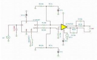
I am trying to amplify an optical signal which comes from a photodetector in the range of 30 µA with a transimpedance amplifier (OPA857) followed by a variable gain amplifier (THS7530). The problem is that the output is experiencing undershoot and I have figured out that this mostly comes from the first stage and maybe is because of the input parasitic capacitance. Followed is the schematic of my design. Is there any way to compensate for this?

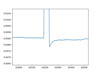
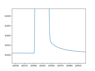
Here is the simulation output when I increase the parallel capacitor to 2pF:

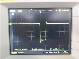
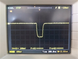
And the circuit output:

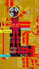
PCB layout: (IC4 is the first op-amp and IC3 the second. PD is the photodetector):

Adding a parallel RC from the output of the first stage to its input (Feedback) compensates the undershoot to some extent but it still remains and is not negligible. It also broadens the pulse width which is not desired.

  • Hi Farzin,

    In order to look more into this and get a better idea as to what is going on could you please provide the Tina file you are simulating with. For your measured result are you probing at the output of the THS7530 or at the output of the OPA857? If so, are you seeing the expected signal at the output of the OPA857? Could you also clarify what is meant by the 2pF capacitor you have been changing. This will be useful in trying to resolve some of these issues you are seeing.

    Best Regards,

    Ignacio

  • Dear Ignacio,

    First I modeled the photodetector(apd) as a current source parallel with a capacitor in the order of 350f which was unrealistically small so I increased the  capacitor to 2pF and the undershoot is now visible (trying to simulate whats happening in my board). I am probing the signal at the output of THS7530.

    I attached the TINA file for your reference. Thank you.

    ti-question.TSC

  • Hi Farzin,

    Thank you for providing the Tina file, after reviewing the datasheet and running some simulations on the circuit I believe your observations are correct that the APD capacitance is causing this undershoot you are experiencing. The OPA857 is optimized for low total input capacitance around 1.5pF. This means that this value includes board parasitics. Any additional input capacitance above 1.5pF from both layout + APD, the device's performance is expected to degrade which is what you are likely seeing in your results. I did see your layout and there doesn't seem to be any major concerns as we recommended putting the pd as close as possible to the input which you did. As a result, the input capacitance is likely from the APD itself. Paragraph one in section 7.1 in the datasheet highlights the idea I mentioned above. Is there a capacitance value the APD datasheet highlights for the component you're using?

    Best Regards,

    Ignacio

  • Hi Ignacio,

    Thank you for your time investigating the probem. The datasheet of the APD declares the value of 0.3pF for its terminal capacitance. That made me doubt if the problem is because of input capacitance which makes OPA857 unstable. So I bypassed the second stage (THS7530) and did the measurement with ADC and there was no undershoot. The Tina simulation for THS7530 as a single amplifier also shows this over/undershoot for pulsed inputs. I couldnt find out the reason for this.

  • Hi Farzin,

    The input capacitance of the APD should not be a concern if it is in that range. This is great debugging work narrowing down the stage. If you see some of the pulse response figures in the datasheet of the THS7530 you see this over/undershoot. When the circuit includes both stages, does this over/undershoot problem change when you increase the gain of the THS7530? Overshoot and undershoot of a device stem from external factors as well as how the device is designed. Behavior, such as step responses, change in different configurations which is why looking at the second stage in a different configuration, if possible, might offer some insight into the issue you are experiencing.

    Best Regards,

    Ignacio

  • Hi Ignacio,

    When the circuit includes both stages, the undershoot decreases with increasing gain and increasing gain more results to a exponential decaying pulse response.

  • Hi Farzin,

    These results make sense as you increase the gain the amplifier will have more phase margin and overall be more stable which results in less over/undershoot. The decay behavior is not captured in the datasheet for this device, however, could you maybe tune the gain of the device to result in a suitable response at your output? In the two-stage circuit when probing the output of the TIA do you see this undershoot or is it only at the output after the second stage?

    Best Regards,

    Ignacio

  • Hi Ignacio,

    Thanks again for your time. Here is the pulse response right at the OPA857 output pin.

    And the following after the R1(in the schematic), so the signal arrives the second stage in good condition I think. Also bypassing the second stage shows no unstable behaviour. ( note that the pulses are inverted)

    Tuning the gain does not compensate for all input pulses with different DC levels. When the input has near zero-level DC(input common mode of THS7530) agian this bahoviour shows up, but with higher DC level it compensates.

    Bests,

  • Hello Farzin,

    Thank you for providing the update to Igancio's questions.  Ignacio is out of office and will be back early next week.

    Please share any updates as you need.

    Best,

    Alec

  • Hello Farzin,

    Do you still require assistance on this thread?

    Best,

    Alec

  • Dear Alec,

    Still workign on the suggestions of Ignacio. I will update with the results.

    Bests,

    Farzin