This thread has been locked.

If you have a related question, please click the "Ask a related question" button in the top right corner. The newly created question will be automatically linked to this question.

LMP7721: LMP7721 Split supplies configuration

Part Number: LMP7721
Other Parts Discussed in Thread: TINA-TI

Hi

I'd like to use the LMP7721 in a split supply configuration eg V = +2.5V and V- = -2.5V

Will this work ok and what negative impact on performance can I expect...?

Note - I tried using the Tina simulator but I'm seeing some peculiar results in practice...

Thanks

Ken

  • A total supply voltage of 5 V is supported. There should be no effect on performance.

    The Spice model might have an error (V− connected to circuit ground or something like that). But what is the problem you see?

  • The simulator seems ok.

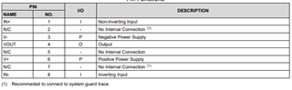
    In practice I'm getting inconsistent measurements. I'm measuring a step input pulse of approximately 0 to +1.5V but the output delta seems to respond inconsistently. I noticed the spec sheet suggests to tie the NC pins to GND - but I left them floating. Should these be tied to the V- supply maybe...?

  • Ken,

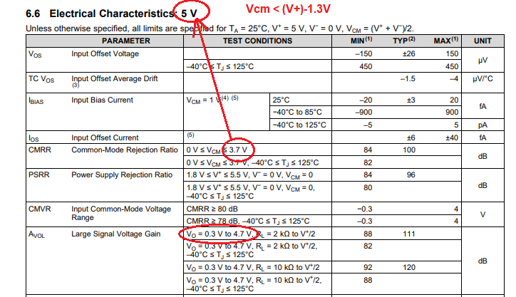
    You do not specify the circuit configuration you use but I believe the issue you see is caused by the violation of LMP7721 input common-mode voltage range, Vcm.  LMP7721 input common-mode voltage is from (V-) >Vcm <(V+)-1.3V (see below) and thus in a buffer (G=1) configuration with +/-2.5V supplies, the valid input linear range is from -2.5V to +1.2V (not +1.5V you use).  Additionally, since the linear output range is 300mV from either rail (see AOL conditions), in a buffer with +/-2.5V supplies the allowable linear voltage range is a combined input/output range of  -2.2V to 1.2V.

  • Hi Marek

    Thanks for the feedback, and note your recommendations, but suspect this is not the complete answer to the problem as I have reduced the applied input but still note unexpected results.

    Some additional details of the circuit configuration....

    The amplifier forms the input stage to an electrostatic field meter. The inverting input to the amplifier is connected to the sensing plate as well as the output of the amplifier via a 200pF capacitor. There is a second 200 pF capacitor connecting the non-inverting input to 0V. Across each capacitor, there is a switch and prior to making a measurement, the switches momentarily close to discharge any residual charge on the capacitors and the output from the amplifier is 0V. The switches are opened and a positive Voltage is then applied to an electrode (not in contact with the sensing plate) but of sufficient magnitude to create an electrostatic field. A Voltage is induced onto the sensing plate and charges the capacitor in the feedback loop. The Voltage on the capacitor is proportional to the charge induced on the sensing plate and the size of the capacitor in the feedback loop. Nominally this is about 1.5V (a negative Voltage on the output of the amplifier). I can reduce this Voltage by increasing the capacitor or reducing the size the electrostatic field but my problem is one of consistency. The Voltage measurement is not consistent. The circuit works - it is a mature design and we are only seeking an alternative opamp due to obsolescence - the existing part is an OPA128LM.

    I am curious about the NC pins. The data sheet infers rather than NC at least two of the pins should be connected to 0V.......

    Are these internally connected to the substrate perhaps and should in my configuration being +/-2.5V be connected to V- rather than ground...? They are open circuit at the moment.

    Thanks for the support.

    Ken

  • Ken,

    LMP7721 NC pins have no internal connection, thus left floating would not cause the problem you see. They are recommended to be connected to system guard trace (NOT ground) only to minimize the input bias leakage current between the pins. 

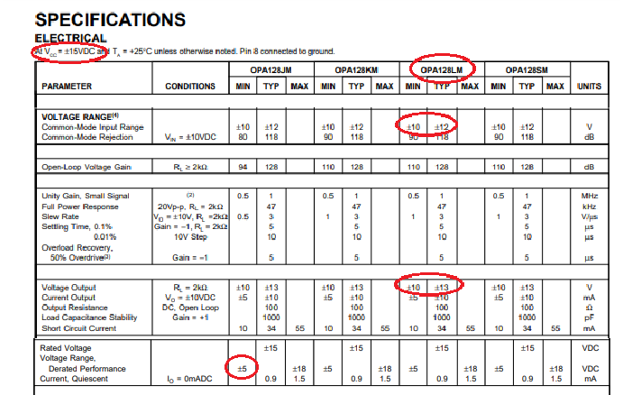
    Having said that, OPA128LM has a minimum supply voltage of +/-5V with the input/output voltage linear ranges of 2V-5V from either rail (see below). Thus, it would never work on +/-2.5V supply. 

    Additionally, it sounds from your description like the signal is AC coupled - since the picture is worth thousand words, please send us the Tina-TI schematic you use for your simulation.

  • It's been more than a week since your last reply.  Thus, I'll close this post for now.  If you have further questions, please reply or start a new thread.