


Written by: Charles Barsh
The electrification of automobiles is rapidly increasing, and as it does, there are more advanced systems integrated into these vehicles. These electrified vehicles contain sensitive GaN and SiC switches that are susceptible to overcurrent conditions. Therefore, there is a need to implement a current monitoring circuit that must react to peak overcurrent conditions, and in many cases, shutdown in less than 1 µs to prevent damage to the switches. Utilizing a high-speed amplifier and comparator based current shunt monitoring circuit, as shown in figure 1, in these applications is advantageous as they ensure the delay time is minimal.
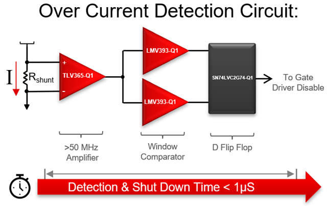
Figure 1: Typical Current Detection Circuit
What is a high-speed amplifier and why should one be used?
The propagation delay of a circuit varies drastically based upon the components selected. If a DC-DC converter uses average current control for power factor correction, for example, then a slower amplifier may be used. However, if there is a need to detect peak current, or if the system needs to react and shutdown in less than 1 µs, then a high bandwidth amplifier is required. In figure 2, the current waveforms of peak detection and average detection are overlaid. The reason using a higher bandwidth amplifier for peak detection is necessary is the fact that the transient current spikes occur very quickly – when measuring average current, these spikes would remain undetected.
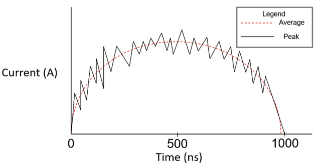
Figure 2: Average Current vs. Peak Current Waveforms
Newer implementations of on-board chargers, DC/DC converters, and traction inverters are taking advantage of the reduced power consumption and faster switching frequencies provided by Gallium Nitride and Silicon Carbide switches. Many GaN switches are susceptible to failure from current spikes over 54A and at a duration of a little as 1 µs. In figure 3 below, the rise times of a 10 MHz and a 50 MHz op-amp are compared, showing that a high bandwidth 50 MHz op-amp reduces propagation delay by 0.8 µs. This allows for ample time to detect and respond to an overcurrent condition.
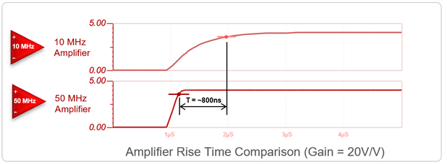
Figure 3: 10 MHz Ideal Rise Time vs. 50 MHz Ideal Rise Time
To achieve detection and shutdown in less than 1 µs, we can allocate 35% of the total response time to the amplification stage. If the amplifier requires a gain of 1 V/V, then the required bandwidth of the amplifier would be 1 MHz; however, most shunt based current monitoring circuits require gains in the range of 50 V/V to reduce the power consumption of the shunt resistor. To achieve this level of gain, an amplifier with at least 50 MHz would be required, as demonstrated in the calculations below.
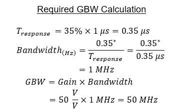
*Note: 0.35 is a constant value used to approximate bandwidth. This is related to the time it takes a capacitor to charge from 10% to 90%. See TI Precision Labs video on Slew Rate here for more details.
Texas Instruments offers a variety of amplifiers for different system requirements. A comparison chart showing the rise times of several amplifiers is shown below in figure 4.
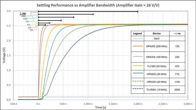
Figure 4: Rise Times of Several TI Amplifiers
Some designers will opt to cascade two or more lower bandwidth amplifiers with different amplification stages in order to achieve the same amplification at a reduced cost. Using multiple lower bandwidth amplifiers adds additional propagation delay and requires more space on their circuit board. High bandwidth amplifiers historically were perceived to be costlier alternatives, however with modern manufacturing capabilities at Texas Instruments, these newer devices are able to be priced more competitively and are comparable to using multiple lower bandwidth amplifiers.
Single Shunt vs. Multi Shunt Current Sensing
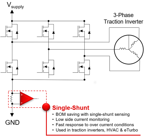
A further way to reduce board space and potentially reduce cost is to implement a single shunt as opposed to using multiple shunts in a system. For a system in which multiple average current measurements are taken, utilizing a higher bandwidth amplifier and tying these measurements together can reduce the number of amplifiers required. However, there are cases in which a multi-shunt configuration is required. For example, if measuring the individual current phases in a three-phase traction inverter is desired, then multiple high bandwidth amplifiers should be implemented to measure the peak current faster. Typical setups of a single-shunt traction inverter and multi-shunt traction inverter are shown below in figures 5 and 6.
|
Figure 5: Single Shunt Implementation; Three Phases Tied Together |
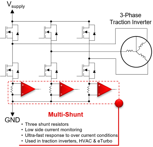 Figure 6: Multiple Shunt Implementation; Each Phase Current Measured Separately |
Conclusion
Detecting and responding to overcurrent conditions in electrified vehicles in sub 1 µs is becoming increasingly important as more efficient GaN and SiC switches are implemented in these systems. When designing a system, choosing the right amplifier can help save board space, money, and reduce delay times. Check out Texas Instruments broad portfolio of automotive qualified high-speed amplifiers that include a wide range of bandwidths and precision.
| Recommended Devices for Automotive Current Sensing Applications | |||||
| Device | Channel Count | Supply Voltage Range (V) | Gain Bandwidth Product (MHz) | Slew Rate (V/μs) | Minimum Stable Gain (V/V) |
| TLV365-Q1 | 1 | 2.2 - 5.5 | 50 | 27 | 1 |
| OPA607-Q1 | 1 | 2.2 - 5.5 | 50 | 24 | > 6 |
| OPA2607-Q1 | 2 | 2.2 - 5.5 | 50 | 24 | > 6 |
| OPA354A-Q1 | 1 | 2.2 - 5.5 | 100 | 150 | 1 |
| OPA2354A-Q1 | 2 | 2.2 - 5.5 | 100 | 150 | 1 |
| OPA4354-Q1 | 4 | 2.2 - 5.5 | 100 | 150 | 1 |
| OPA2863-Q1 | 2 | 2.7 - 12.6 | 50 | 105 | 1 |