This thread has been locked.

If you have a related question, please click the "Ask a related question" button in the top right corner. The newly created question will be automatically linked to this question.

OPA858: Amplifier Develops Unstable Ringing Behavior After Some Time

Part Number: OPA858
Other Parts Discussed in Thread: OPA855

Hello,

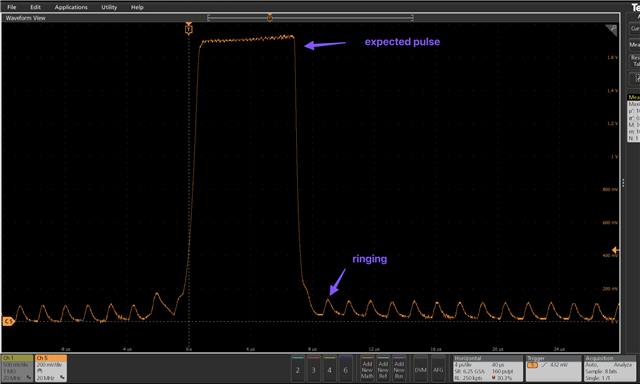
We are currently using the OPA858 in a simple trans impedance amplifier circuit as below. The photodiode sees photons of scattered laser light and we use the OPA 858 as a fairly standard TIA as below. The system operates nominally (we are able to run at high gains, clipping the max positive level) for a period of time, however after some time (hours) the amplifier seems to exhibit ringing behavior (but still sort of functions). The ringing behavior seems to develop gradually (after some hours of service) and at first the ringing is intermittent, however as time goes on it seems to become more permanent (suggesting possible gradual damage to the amplifier).

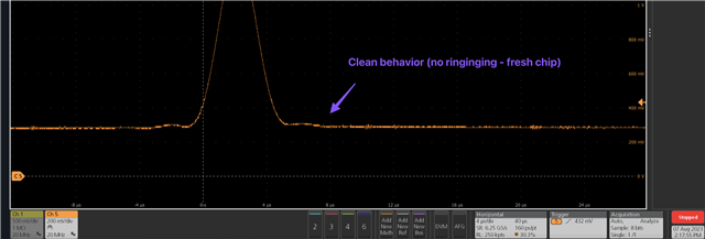
Powering off the amplifier (when it is ringing) and lowering the laser power and powering it on results in clean operation, however as soon as (the aged chip) sees a clipped signal - it will start ringing very quickly. New amplifiers are able to see a clipped signal and operate nominally for some hours (leading us to suspect some gradual damage is being possibly done)


For maximum sensitivity reasons - it is desirable in our application to run with the laser power set as high as possible and the Rf gain set as high as possible. In this case - the amplifier is nearly always "clipping" the positive pulse (the pulse output fully runs to the max level as the photo diode receives a lot of light during its pulse).

This issue has been replicated on two separate boards and replacing the OPA858 on the PCB with a new one seems to make this issue go away for a while.

In order to check there was ample margin - adding  pF amounts of Cf (in parallel to the Rf feedback resistor) does not make the ringing go away - but does of course limit the system bandwidth in an undesirable way.


Is this amplifier particularly sensitive to being overdriven (I.e so much light received at the PD that the output basically looks like a positive going square wave that hits the rail)?

Do you have any suggestions for how we may further isolate the problem?

Are there ways you suggest protecting the amplifier (if this is indeed the problem) so that we can operate it in this mode, or an alternative part that may not face this issue?

EDIT : Tried this with an OPA855 and still seeing similar behavior (lowered the gain) - it may not be damage but trying to figure out what causes the amp to become unstable . 
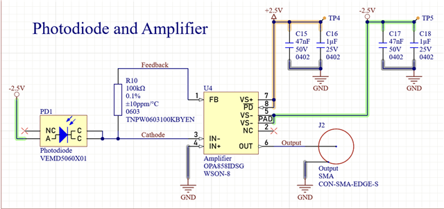
  • Hi Matthew,

    What is the value of photo diode current when laser is set to max power?

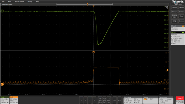
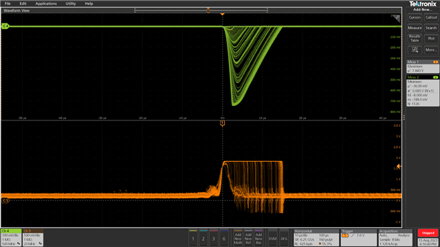
    Can you please measure and let us know the inverting input pin voltage (pin3 of OPA858) when output clips at max laser power?

    Regards

    Anant

  • the photo diode current is estimated to be on the order of 30uA 

    Attached below are scope captures - the green trace is the IN- pin and the orange trace is the output J2  

  • Hi Matthew,

    I will review this and get back to you by Friday.

    Regards

    Anant

  • Hi Matthew,

    We are looking into this, but need some more time to debug it, will revert back by end of this week.

    Regards

    Anant

  • it seems that reducing the rails from +/- 2.5V to +/- 2V improved things (we havent been running for very long but it looks promising) - not sure if this is a clue for you but we suspect somethings going on in the chip (we can speculate here but not knowing the actual architecture of the chip we are not sure - let us know if you want "damaged" samples for FA/imaging) 

  • another datapoint is that it appears to also behave okay with +2/ -2.5

     (I suspected that since our pulse is hitting the positive rail that it might be that segment of the system that is failing)

  • Matthew,

    Since none of the pin voltage is exceeding the abs max limit, it should not cause any damage to the device.

    I am trying to replicate the same test condition here in our lab and see it is causing any damage,.


    Regards

    Anant

  • Hi Matthew, 

    What size of feedback capacitor did you try with the 100k resistor. The circuit does need some feedback capacitance to operate without oscillation and this does seem to me like an instability issue. It may be that the on-board capacitance is enough at first but as the chip heats up or ages in a little it becomes unstable. 

    Because the input capacitance is fairly large from the diode at 35pF the acceptable total feedback capacitance range is quite small at about 0.2 to 1.5pF. 

    Regards, 

    Jacob 

  •   Can you offer any insight why running the chip at -2.5V and +2V (for it's supply rails) and changing nothing else about the system seems to make it perfectly happy evening running for long periods of time (running at +/-2.5 seems to yield failure in about 2-3 hours on average, but just lowering the positive rail down to 2V it was stable for multiple days so far. 

    We did try 0.5 and 1pF capacitance as well as some intermediate values and this didn't seem to help. 

    Would you like me to decap/image/delayer/FIB the defective chips and post here? If so let me know what to look for and I'll get to it. I could also construct some of the same test fixtures you guys use in the data sheet and attempt a A/B characterization of the broken versus a fresh new chip?

  • Matthew,

    Firstly can you check Iq and input bias current in the damaged chip? How it changed from the fresh chip?

    To further root cause it, it would be better if you can ship some damaged unit to us. I will contact you separately over email for that.

    Regards

    Anant