This thread has been locked.
If you have a related question, please click the "Ask a related question" button in the top right corner. The newly created question will be automatically linked to this question.
Hello TI
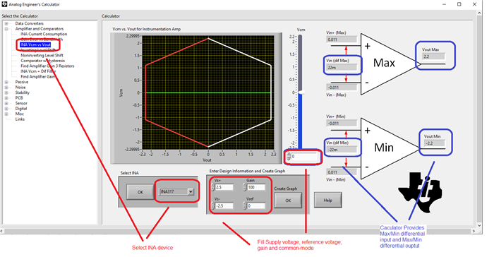
We are designing the current sense circuit using INA317 for high side sensing to measure current for 3A, 10 A and between 3A to 10 A . The question is, Can we design current sense circuit in which load current at the input side connected at the lower end of Rsense, is in microamps? I am not getting any document based on INA 317, for designing precise current sense circuit which includes how to select Rsense value, what is the maximum range of the current flow in load. If such a document is available, please share the link.
HI Sonal,
The maximum differential voltage that can be supported by the instrumentation amplifier depends on the input common-mode voltage, the V+, V- voltage supplies, the instrumentation amplifier gain, and INA317 reference pin voltage.
The "VCM vs Vout for Instrumentation amplifier" is a tool used to verify the instrumentation amplifier is within its linear region. The “Vcm vs. Vout” software tool considers the input and output limitation of each internal amplifier and displays a system level graph showing the linear output range as a function of input common-mode voltage.
For example, in a low-side shunt resistor application, where the shunt resistor is grounded, the INA317 requires bipolar supplies to keep the INA input common-mode inside the specified range. In the quick example below, when configuring the INA317 with bipolar +/-2.5V supplies, VREF=0, Gain = 100V/V, and assuming input common-mode voltage 0V, the max/min differential voltage allowed across RSHUNT is ±22mV, and the output voltage range is ±2.2V with respect to GND.
Regarding to the tool, you may download the Analog Engineer's calculator in the link below. The "Help" button on the "VCM vs Vout for instrumentation amplifier" tab provides a more detailed explanation.
www.ti.com/.../ANALOG-ENGINEER-CALC
Hence, the Rsense resistor value is selected according to the minimum and maximum current range you need to measure, while accounting for the minimum/maximum differential input voltage that can be supported on the instrumentation amplifier input, while keeping the instrumentation amplifier within is optimal linear region. In the case of the INA317, please note that the input common-mode voltage needs to be within the voltage supplies of the INA314, and more than 0.1V above and below the supplies. For best/optimal range, the common-mode voltage range ideally would be centered at the middle of the supplies.
-What is the input common-mode voltage? In other words, is this a low-side Rshunt current sense application where the RSHUNT resistor is grounded or what is the common-mode voltage with respect to GND? What is the min and max current you need to measure across the shunt? What output voltage range do you require? What voltage supplies are available/possible in the system?
Thank you,
Regards,
Luis
Thanks Luis Chioye.
Your reply has solved my different quires regarding INA317.
Actually, we are designing current sense amplifier using INA317 with high -side Rshunt(Rsen) current sense application as in diagram. Our requirement is to design circuit using INA 317 measuring output 1)3A , 2)>10A and 3) from 3A to 10 A. So here we are going to use I to V concept.
And we want that the load connected with Rshunt(Rsen) should measure current in terms of microamps.
Hi Sonal,
Thank you. The high-side Rshunt setup above is only possible with the INA317 as long as the Rsen common-mode voltage is within the range of the INA317 supply.
Please ensure to verify the range with the "VCM vs Vout for Instrumentation amplifier" tool, as the INA317 circuits input common-mode requires more than 0.1V headroom below the (V+) supply. If you would like us to verify the circuit, let us know the Power Supply voltage of the Rsen resistor, as well as the INA317 voltage supplies and reference voltage.
Thank you and Regards,
Luis
Hello Luis,
Thanks again for reply. Mostly we are keeping Rsen either 0.01 ohm or 0.1 ohm. The power supply of the Rsen resistor voltage 4.6 volt and INA 317 voltage supplies only positive supply + 5-volt, negative supply 0-volt, reference voltage 2.5 volt.
Hi Sonal,
Since your common-mode voltage is relatively high at 4.550V, close to the positive supply, you may consider increasing the INA317 supply to +5.5V, which allow headroom to use higher gain on the instrumentation amplifier.
Thank you and Best Regards,
Luis