This thread has been locked.

If you have a related question, please click the "Ask a related question" button in the top right corner. The newly created question will be automatically linked to this question.

INA118: Alternative for strain gauge signal amplification with offset compensation at input signal

Part Number: INA118
Other Parts Discussed in Thread: INA188, PGA308, PGA309

Hi, 

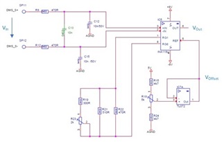
we are using the INA118 for amplification of a strain gauge force sensor. The unloaded sensor output voltage can vary between +64mV to -64mV due to tolerances of sensor and due to forces applied during application. As we need a gain of round about 500, the strain gauge need to be compensated by a manually adjusted bridge balancing element to adjust the sensor output voltage to less than 2µV. 

As the INA118's output is G*(Vin+ - Vin-) + Voffset, the "allowable" offset at the input for high gain settings is fairly low... For 5V single supply and Gain of 500, 1mV offset (Vin+ - Vin- = 1mV) would already end up with 0,5V Output voltage, which needs to be adjusted by the Ref. Voltage)... 

I assume an instrumentation amplifier adding the external offset adjustment to the input voltage, i.e., Vout = G*(Vin+ - Vin- + Voffset) should support easier adjusment while - for sure - require stable offset voltage as any offset drift (due to temp. etc.) will be amplified as well.. 

As there seems no such amplifiers avaible, am I wrong with my assumption, or, will such kind of "stable offset" voltage be impractical to achieve?

KR

  • Hello Carlhermann,

    You are correct, the easiest way to perform offset calibration is to adjust the reference voltage. Ensure you drive the reference pin with low impedance. 

    This kind of "stable offset" over time and over temperature is difficult to achieve but is best approached with a zero-drift device. See this app note on zero-drift technology: https://www.ti.com/lit/an/sboa182c/sboa182c.pdf and you may check out our high voltage zero-drift INA - INA188. 

    Another approach is build a discrete INA with zero-drift op amps, in which case we have many options: https://www.ti.com/amplifier-circuit/op-amps/precision/products.html#480=1&2192=Zero%20Drift&1261max=6%3B180&

    Please let me know if you have any additional questions.

    -Brittany

  • Hi,
    my main problem is, that I'd like to correct the offset at the input signal and amplify the offset corrected input signal, i.e. Vout = Gain x (Vin+ - Vin- - Voffset) rather amplifying the input signal offset by 500 first, thus requiring a offset voltage adjustment range of 500 times the input signal's offset... 

  • Hey Carlhermann, 

    Can you provide a schematic and part numbers to help us better understand the design challenge. 

    Best Regards, 

    Chris Featherstone

  • Hi, for sure :-) 

    As the output voltage is referenced to GND, the input signal is to be amplified and also shifted by 2.5V offset, i.e., Vin = 0mV => Vout = 2.5V. 

    As we need a Gain of round about 500 an input voltage offset range of e.g. +/-2mV requires the offset voltage to be adjustable between 1V and 4V. That makes the potentiometer for offset adjustment (single turn, 250° angle) much too sensitive...
    Theoretically (due to tolerances of the strain gauges), the offset of Vin could vary between +/-64mV.. 

    If the offset adjustment would have effect on the input voltage rather the amplified input voltage, the offset would be easily adjustable...

    Best regards, Carlhermann  

  • Hi  Carlhermann,

    One popular device for this type of challenge is the PGA308 or the PGA309, which is an instrumentation amplifier family with programmable gain and offset calibration. The PGA308 provides an analog output, it amplifies the sensor signal and provides digital calibration for offset and gain.

    On the PGA308, calibration is perform via the 1W pin, a digital UART-compatible interface. Gain and offset calibration parameters are stored onboard in seven banks of one-time programmable (OTP) memory. Therefore, the device requires programming of one-time programmable OTP calibration settings through a 1-wire UART interface.

    If the offset adjustment would have effect on the input voltage rather the amplified input voltage, the offset would be easily adjustable...

    The internal PGA308 DAC allows you to inject a coarse cancellation offset  before gaining up the signal, see below:

    You can learn more about the PGA308 and PGA309 on the video below.

    https://www.youtube.com/watch?v=oVvg1tfVt28

    PGA308 User's Guide (Rev. B)

    Thank you and Regards,

    Luis

  • Hi Luis, 
    looks like the PGA308 would be the device to use in case of an upgrade of the sensor's electronics :-) 

    I'll keep this in mind, currently we are stuck with the current design, which seems to require offset calibration within the sensor's elements. 

    Kind regards, Carlhermann 

  • Hi Carlhermann, 

    Can you provide the datasheet for the sensor to help us understand it's parameters? If not, would you be able to clarify the following:

    1. The sensor's offset voltage
    2. The sensor's full scale range
    3. The impedances of the sensor

    Coming up with a discrete design to perform the same functions as the PGA308 could turn into a very elaborate design and come with many trade offs. Either a precision current needs to be pulled from one of the legs or a precision voltage needs to be applied. If you can help us clarify the sensor parameters above we can try to brainstorm some ideas. Currently our best recommendation is the PGA308.  

    Best Regards, 

    Chris Featherstone