Part Number: XTR111
Other Parts Discussed in Thread: OPA189, TINA-TI, OPA828, OPA328, OPA827, OPA140, OPA3S328, OPA320
Hello,
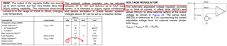
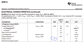
as you can see in the picture below in the datasheet of the XTR111 it says that the minimum current output of the integrated regulator is 5mA.
Later on in the datasheet it says that 5mA is the maximum current the integrated regulator can source.
What is correct?
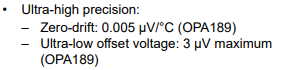
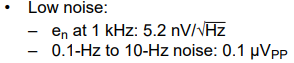
I want to supply an OPA189 with it, which has an Icc,max of 1.8mA but as the OPA189 will be a part of a TIA configuration, 5mA might not be enough.
Or can the integrated regulator source more than 5mA of current?
I would really like to avoid the suggested external solution from figure 45c as space is very limited in my design.
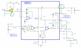
I just tried to set up a simulation with the XTR111 in Pspice but there doesn't seem to be a simulation model for the XTR111.
Best regards,
Stephan