This thread has been locked.

If you have a related question, please click the "Ask a related question" button in the top right corner. The newly created question will be automatically linked to this question.

INA826: Problem with extra offset

Part Number: INA826
Other Parts Discussed in Thread: INA286,

Hi Everyone,

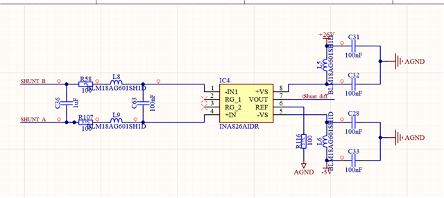
I am using INA826 for current measurement. Input SHUNT_A and SHUNT_B is connected to 100R resistor for current 0-10 mA.
I have problem because when current circuit is open (current is equal to  0 mA) a have output offset 21 mA on INA826.
INA286 is powered -5V  to  (-26) V.
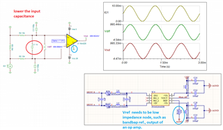
When i use for simulations  TINA software this problem doesn't exist, everything will work ok.
All devices is connect to the same GND.

  • Hi Filip,

    I have problem because when current circuit is open (current is equal to  0 mA) a have output offset 21 mA on INA826.

    The input connection to the INA826 has to be connected to establish a proper common mode voltage,  Vcm. Since you have +26Vdc/-5Vdc as Vcc and Vee, the Vcm = GND =0 is ok, but the input can not be floating.

    I simulated the circuit in Tina. Please keep the input capacitance low. The circuit has the differential mode LPF at approx. 8kHz, I left the same by changing R and C. Also, I add common mode LPFs. 

    The Vref node needs to be low impedance, <1-5 Ω impedance for the part. You may connect it GND since you have dual supply rail. The Vout's transfer function is Vout = Gain*Vdiff + Vref, where Vref = GND = 0V in the simulation, and Gain = 1 V/V.  

    INA826 E2E 08162023.TSC

    Here is the INA826EVM user's guide, please check it out. 

    https://www.ti.com/lit/ug/sbou115c/sbou115c.pdf?ts=1692192807099&ref_url=https%253A%252F%252Fwww.google.com%252F

    If you have other questions, please let me know. 

    Best,

    Raymond