A related question is a question created from another question. When the related question is created, it will be automatically linked to the original question.
If you have a related question, please click the "Ask a related question" button in the top right corner. The newly created question will be automatically linked to this question.
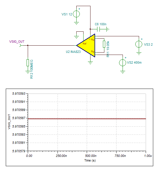
We are expecting to see 10V output but we keep getting 5.97V output.
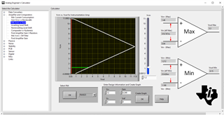
Currently, the circuit is operating in this region, see the Vcm in the green line, and it is unable to swing up to 10Vpk.
Could you provide me with the design requirements? For instrumentation amplifier (IA), your Vcm is configured at 1.2Vdc (a bit low)and your input signal swing is large with respect to the supply voltage. I was wondering why you are selecting the IA, not difference amplifier or other topologies.
If the Vcm is low, you may need to use dual voltage supply rails.
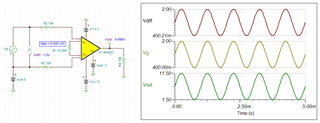
Here is an example of the circuit with the output voltage swing you may need. Since I do not have the design requirements, pls consider this as an example to reach the output swing with 12Vdc at the gain.
many thanks for your reply. Essentially we want to use the INA823 to transform a 0.4-2V signal into a 0-10V signal using a single 12V supply if possible.
What would be the preferred way of doing this? Our solution from above clearly doesn't seem to work.
If the single supply design doesn't work, we're open to the idea of having a negative supply as well even though we're not too happy about the additional effort to generate it.
we have a single ended input signal (coming from another part of our design) with a rage between 0.4V to 2V. We need to shift it by 0.4V and then scale it by factor 6.25 into a single ended output signal ranging between 0-10V. Essentially an input signal with 0.2V should result in an output signal of 0V, an input signal of 1.2V should result in an output signal of 5V and an input signal of 2V should result in an output signal of 10V. The output will be transmitted over a BNC connector and a 50Ohm coax cable to an external oscilloscope for inspection.
How about the difference amplifier instead. OPA192 maybe overkill, I can find you a low cost and Vos op amp.
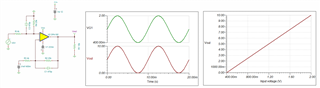
I also implemented LM7705, -0.233V charge pump as supply regulator. This will guarantee that the output will be 0mV. If you do not care of about a few to 10s mV offset voltage at output, then LM7705 is not needed. The negative voltage is generated from positive voltage supply rail. The feedback resistors in the difference amplifier needs to be 0.1% or better in tolerance.
I can still make INA823 work, but it may need play around the Vcm and negative supply rails.
Alternatively, we can level shift the signal by 0.4Vdc, then convert the input signal to current, like V-I converter (0-20mA loop current) in XTR111. At the end of BNC cable, we can use 500ohm resistor to convert it back to 0-10V signal (if the BNC cable is long, say 10 meter or longer, the V-I transmitter will be a better options).
These are the options. Please let me know what you think.