This thread has been locked.

If you have a related question, please click the "Ask a related question" button in the top right corner. The newly created question will be automatically linked to this question.

XTR115: Design schematic for two pin sensor

Part Number: XTR115
Other Parts Discussed in Thread: XTR117, XTR116

Hello,

I want to design a 2-wire transmission line by XTR115. But my sensor is not a bridge sensor. I need a schematic to show me how can I connect the sensor with v- and v+ to the IC. 

Thank you so much

  • Hi Hannaneh,

    I need a schematic to show me how can I connect the sensor with v- and v+ to the IC. 

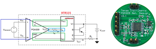
    This is a good block diagram. XTR115/XTR116/XTR117 are all 2-wire current loop transmitter. For the 2-wire current loop transmitters, here are the important design parameters.

    1. The sensor and/or op amp has to be powered by XR115 via Vreg, and the current has to be <3.7mA, say at 5Vdc. 

    2. Sensor and/or op amp's ground is floating, and shall return to Iret node. Iret is considered floating GND. The actual Vloop GND is located at Vloop. Only one GND node is required in 2-wire type of current loop transmitter. 

    3. Vsensor and/or op amp can not have its GND as stated in line item 2, The analog front end is floating and it is connected with respect to Iret node or floating node. 

    https://www.ti.com/lit/ug/slau526/slau526.pdf?ts=1692223647342&ref_url=https%253A%252F%252Fwww.google.com%252F

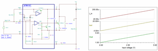
    Enclosed is a typical XTR115 simulation and V-to-I conversion characteristics. You should check out the simulation, then add your sensor and/or op amp to the input front end. Please keep in mind that the sensor and/or op amp's analog front end has to use a low power current consumption components, which the total system's current consumption is < 3.7mA when there is zero  or NO input signals. .   

    XTR115 E2E 08162023.TSC

    If you have other questions, please let me know.

    Best,

    Raymond

  • Thank you so much for your guidance and support.