This thread has been locked.

If you have a related question, please click the "Ask a related question" button in the top right corner. The newly created question will be automatically linked to this question.

OPA567: Design review

Part Number: OPA567

Hello,

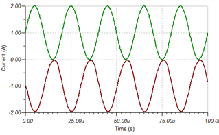
My customer designed an LD (Laser Diode) drive circuit(0A~2A) as shown below using the OPA567 and checked the simulation results as shown on the right through TINA tool.

However, when the actual circuit is implemented and tested, there is a problem that it does not operate like the simulation result and does not output.

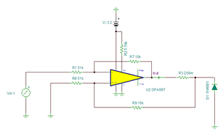
Please review whether there is a problem with the circuit.

Thank you.

JH

  • JH,

    Here are some things that I checked on your circuit:

    1. Stability - see simulation below.  I don't see any stability problems.
    2. Common mode range - Your common mode signal ranges from -0.6V to 0V.  This is is inside the range: -3.4V < Vcm < 0.1V so common mode looks ok.
    3. Output swing limit - the output swing limit is 0.2V for light load and good linear response, and 0.3V under heavy load.  So, technically, you are close to this limit and/or violating this limit for low current levels.  You can confirm if this is a problem or not.  The diode voltage jumps up fairly rapidly when even low levels of currents are applied so as long as the diode drop is 0.3V or greater you should be ok.
    4. I looked at the enable, Tflag, and Iflag pin descriptions.  I believe you are using these pins inside the specified limits.
    5. I looked at the supply configuration.  Using a negative supply and no positive supply is a somewhat unusual configuration, but I really don't see any detail in the data sheet that precludes this type of operation.
    6. In summary, I don't see any issue based on the data sheet or simulations.  Can you describe the specific behavior that you are seeing?  Do you have some functionality?  What are the output voltage levels?  Are you using decoupling capacitors that are close to the supply pins?  You should double check all the pin connections to make sure something is not mis-wired.  
    7. Are you connecting the power pad?  This should be connected to the negative supply.
    8. I do not have hardware currently.  However, once you answer item 6, I can order hardware and set this up in the lab and try and replicate your problem in the lab.
    9. Below are the simulation files I used for the verifications above.

    opa567-current pump laser diode.TSC

    stability test - autosave 23-08-22 10_52.TSC

    Best regards,

    Art