This thread has been locked.

If you have a related question, please click the "Ask a related question" button in the top right corner. The newly created question will be automatically linked to this question.

OPA188: Unipolar to Bipolar Conversion

Part Number: OPA188
Other Parts Discussed in Thread: OPA4277,

Hi Team, 

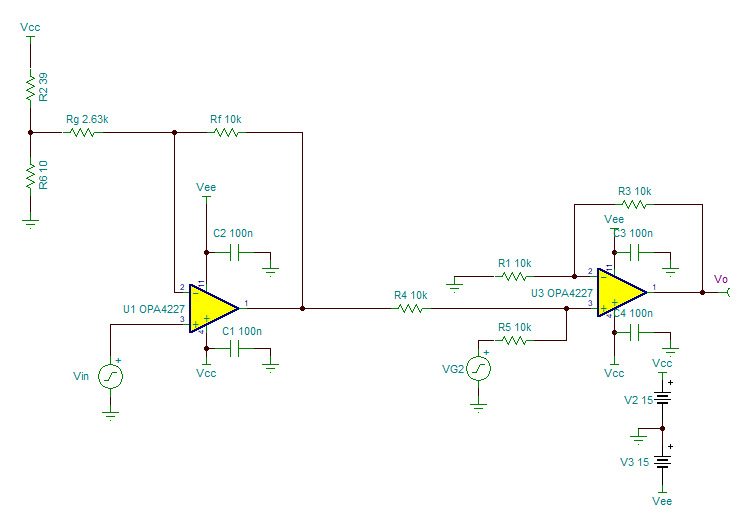
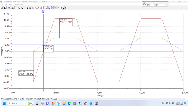
I am planning to use the Arduino Uno R4's DAC pin (A0) (unipolar, 5V) for controlling the Joystick. The input of Joystick is Bipolar. Range is +12V to -12V. So, can you please suggest the amplifier circuit for this.

Thanks.

  • Vimukth,

    1. The PDF below shows the circuit, calculations and simulations.  The first slide shows the ideal circuit.  The second slide shows the practical circuit  
    2. The simulation files are also given below.

    level shift.pdf

    ideal level shift.TSC

    level shift with standard values and reference.TSC

    Best regards,

    Art

  • Hi Art Kay

    Thank you for your suggestion. Let me know, Can I use OPA4277PA, instead of OPAX188. How will it affect the performance?

    Thank You!

  • John,

    Yes, the OPA4277 is a good choice.  Both devices have good offset, and offset drift.  The OPA4277 is a bipolar device, and the OPA188 is a chopper CMOS amplifier.  The key characteristic on chopper amplimers is that they have good offset and offset drift.  The chopper achieves the good offset by internal calibration and the bipolar achieves it by trimming the die. 

    Art

  • Thank You so much Art Kay. 

  • Dear Art kay, 

    One more clarification I required. My Application is to control the Joystick movement. Already the user can control the joystick through it's liver. and for some other purpose, need to control through externally. For that purpose, the output of DAC, giving to the wiper pin of Potentiometer. 

    But, I can't give both at the time, some switching in between is required, correct? Because of loading issue. But I can't use switch or multiplexer here. So I am planning to use summing amplifier here. The signal coming already in the Wiper pin of system is giving as one input of summing amplifier and another input is DAC output. 

    Here I am attaching the design files for same, can you please check and tell your suggestions/observations. 

    Thanks
      JYstk_design.TSC

  • Vimukth,

    • I assume that the DAC input is Vin and the liver input is Vg2.  Is "liver" a typo?  I'm not really sure how a liver would control a joystick, but I guess this isn't important in the circuit design.
    • This seems like a reasonable approach to me.  To "disable" the DAC input you would set the DAC output to 0V.  This would then allow the Vg2 input to drive a signal into U3.  However, in the case where the DAC needs to control the liver would also need to output a specific fixed voltage. 
    • If both the DAC and liver output signals simultaneously, or if the output of one is indeterminant you will not get a predictable output.  The key requirement for this to work is that the signal that is not active will need to be in a predictable state.
    • If you tested your different scenarios and are satisficed that the control meets your needs, then you should be ok.  I think the important thing you need to double check is whether or not the dormant signal stays at a predictable level. 

    Best regards,  Art 

  • Art, 
    1. Yes, Vin is DAC input and Vg2 is wiper pin of Pot in Joystick. 
    2. In the default condition, the Vg2 is 0V and when moving up, it's 0 to +12V voltage level and when moving down, it's 0 to -12V voltage level. So this state is fixed. For DAC, we can set the output range. 
    3. Both DAC and standalone joystick, we are not moving simultaneously. so, that won't be an issue. 

    But when I am simulating, I am setting DAC input Vin to 0V and giving -12V to 12V range to Vg2, but output is not coming properly. 
    Because, the U1 is acting as an inverting amplifier and giving that output voltage to U3. So, predicted output is not getting Vout. Can you please guide me on this, how to avoid this. 


    Thanks 

  • Hey Vimukth, 

    Art is out of the office today and will be able to provide further assistance tomorrow. 

    Best Regards, 

    Chris Featherstone

  • Vimukth,

    I think the problem is that when the DAC is set to 0V, the circuit output is defined as -12V.  The DAC operation is 0V translates to -15V, 2.5V translates to 0V, and 5V translates to +15V.  Thus when you set the DAC to 0V, and apply the joystick signal the DAC circuit output is trying to achieve -12V.

    The solution is to set the DAC to 2.5V so that the output of the DAC circuit wants to be zero.  I re-ran the simulation with this case and it produces -12V to +12V when the joystick swings from -12V to +12V and the DAC = 2.5V.  When the Joystick is at 0V and the DAC swings from 0V to 5V the circuit also outputs -12V to +12V.

    joystick and dac.TSC

    I hope this helps.  Best regards, Art

  • Dear Art, 

    This cleared my doubt. 

    Thanks for your kind information and support. 

    One more query, when giving reference voltage,  " A buffer is needed or the divider will interact with Rg". Can you please tell how it's affecting. 

    Regards
    Vimukth

  • Vimukth,

    Technically, the gain of this circuit is {Gain = Rf/(Rx + R1 || R2) +1 }.  This is where R1 and R2 are effectively in parallel with each other and in series with Rx.  If you keep R1 || R2 very small in comparison to Rx the error introduced by the divider will be minimal.  On the other hand if they are comparable in value the error will be significant.  One way to avoid this issue is to place a buffer between the divider and Rx.  In this case, the gain will be Rf/Rx + 1.  This is why I set R1 = 1.15, R2 = 340, and Rx = 26.3k.  Notice that Rx is significantly larger than R1 || R2.  This example configuration works but the divider will use a lot of current and the feedback network may be larger than you want from a noise perspective.  Note that large resistors will generate noise.

    Long story short:  You don't need the buffer if you make Rx >> R1 || R2, but you may want the buffer if you want to use Rx on the same order as R1 and R2.

    Best regards,  Art

  • Okay. Got it. 

    Thank you so much.